background image

ASUS P5GV-MX

1-27

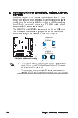
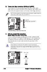
7.  USB 2.0 ports 3 and 4. These two 4-pin Universal Serial Bus (USB) 

ports are available for connecting USB 2.0 devices.

8.  USB 2.0 ports 1 and 2. These two 4-pin Universal Serial Bus (USB) 

ports are available for connecting USB 2.0 devices.

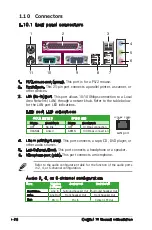
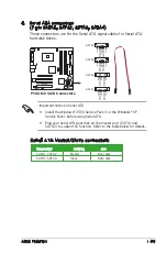
9.  VGA port. This 15-pin port connects to a VGA monitor.
10.  Serial connector. This 9-pin COM1 port is for serial devices.
11.  PS/2 keyboard port (purple). This port is for a PS/2 keyboard.

1.10.2 Internal connectors

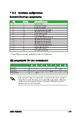
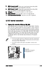
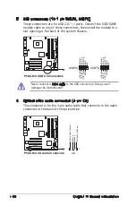
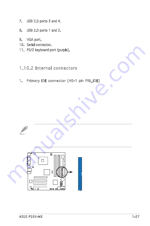
1.  Primary IDE connector (40-1 pin PRI_IDE)

This connector is for an Ultra DMA 100/66/33 signal cable. The Ultra 

DMA 100/66/33 signal cable has three connectors: a blue connector 

for the primary IDE connector on the motherboard, a black connector 

for an Ultra DMA 100/66/33 IDE slave device (optical drive/hard disk 

drive), and a gray connector for an Ultra DMA 100/66/33 IDE master 

device (hard disk drive). If you install two hard disk drives, you must 

configure the second drive as a slave device by setting its jumper 

accordingly. Refer to the hard disk documentation for the jumper 

settings.

•  Pin 20 on the IDE connector is removed to match the covered hole 

on the Ultra DMA cable connector. This prevents incorrect insertion 

when you connect the IDE cable.

•  Use an 80-conductor IDE cable for Ultra DMA 100/66/33 IDE 

devices.

P5GV-MX

®

P5GV-MX IDE Connector

NOTE: 

Orient the red markings

(usually zigzag) on the IDE

ribbon cable to PIN 1.

PRI_IDE

PIN 1

Содержание Motherboard P5GV-MX

Страница 1: ...Motherboard P5GV MX ...

Страница 2: ...TICULAR PURPOSE IN NO EVENT SHALL ASUS ITS DIRECTORS OFFICERS EMPLOYEES OR AGENTS BE LIABLE FOR ANY INDIRECT SPECIAL INCIDENTAL OR CONSEQUENTIAL DAMAGES INCLUDING DAMAGES FOR LOSS OF PROFITS LOSS OF BUSINESS LOSS OF USE OR DATA INTERRUPTION OF BUSINESS AND THE LIKE EVEN IF ASUS HAS BEEN ADVISED OF THE POSSIBILITY OF SUCH DAMAGES ARISING FROM ANY DEFECT OR ERROR IN THIS MANUAL OR PRODUCT SPECIFICAT...

Страница 3: ...rd layout 1 8 1 6 Central Processing Unit CPU 1 9 1 6 1 Installing the CPU 1 9 1 6 2 Installing the CPU heatsink and fan 1 12 1 6 3 Uninstalling the CPU heatsink and fan 1 14 1 7 System memory 1 16 1 7 1 Overview 1 16 1 7 2 Memory Configurations 1 16 1 7 3 Installing a DIMM 1 19 1 7 4 Removing a DIMM 1 19 1 8 Expansion slots 1 20 1 8 1 Installing an expansion card 1 20 1 8 2 Configuring an expansion...

Страница 4: ...Configuration fields 2 13 2 2 7 Pop up window 2 13 2 2 8 Scroll bar 2 13 2 2 9 General help 2 13 2 3 Main menu 2 14 2 3 1 System Time 2 14 2 3 2 System Date 2 14 2 3 3 Legacy Diskette A 2 14 2 3 4 Primary Third and Fourth IDE Master Slave 2 15 2 3 5 IDE Configuration 2 17 2 3 6 System Information 2 18 2 4 Advanced menu 2 19 2 4 1 JumperFree Configuration 2 19 2 4 2 USB Configuration 2 21 2 4 3 CPU Confi...

Страница 5: ...Software support 3 1 Installing an operating system 3 2 3 2 Support CD information 3 2 3 2 1 Running the support CD 3 2 3 2 2 Drivers menu 3 3 3 2 3 Utilities menu 3 4 3 2 4 ASUS Contact information 3 5 Appendix CPU features A 1 Intel EM64T A 2 Using the Intel EM64T feature A 2 A 2 Enhanced Intel SpeedStep Technology EIST A 2 A 2 1 System requirements A 2 A 2 2 Using the EIST A 3 A 3 Intel Hyper T...

Страница 6: ...ause harmful interference to radio or television reception which can be determined by turning the equipment off and on the user is encouraged to try to correct the interference by one or more of the following measures Reorient or relocate the receiving antenna Increase the separation between the equipment and receiver Connect the equipment to an outlet on a circuit different from that to which the...

Страница 7: ...n your area If you are not sure about the voltage of the electrical outlet you are using contact your local power company If the power supply is broken do not try to fix it by yourself Contact a qualified service technician or your retailer Operation safety Before installing the motherboard and adding devices on it carefully read all the manuals that came with the package Before using the product ma...

Страница 8: ... the BIOS Setup menus Detailed descriptions of the BIOS parameters are also provided Chapter 3 Software support This chapter describes the contents of the support CD that comes with the motherboard package Appendix CPU features The appendix describes the CPU features and technologies that the motherboard supports Where to find more information Refer to the following sources for additional informat...

Страница 9: ...at you MUST follow to complete a task Bold text Indicates a menu or an item to select Italics Used to emphasize a word or a phrase Key Keys enclosed in the less than and greater than sign means that you must press the enclosed key Example Enter means that you must press the Enter or Return key Key1 Key2 Key3 If you must press two or more keys simultaneously the key names are linked with a plus sig...

Страница 10: ...400 333 MHz DDR DIMMs 1 x PCI Express x16 slot max 2GB s x4 mode 3 x PCI slots Note Make sure to use only qualified graphics cards Refer to page 1 22 for qualified PCI Express graphics cards list Integrated Intel Graphics Media Accelerator 900 1 x Ultra DMA 100 66 33 4 x Serial ATA ADI AD1986A SoundMAX 6 channel HD audio CODEC Supports Jack Sensing and Enumeration Technology S PDIF out interface Rea...

Страница 11: ...onnector 2 x USB 2 0 connectors for 4 additional USB 2 0 ports 1 x CD audio in connector 1 x Front panel high definition audio connector 1 x S PDIF out connector System panel connector WfM 2 0 DMI2 0 WOL by PME WOR by PME SM Bus Userʼs manual UltraDMA cable FDD cable I O shield 1 x Serial ATA cable 1 x Serial ATA power cable Micro ATX form factor 9 6 in x 9 6 in 24 5cm x 24 5cm Device drivers ASUS ...

Страница 12: ...xii ...

Страница 13: ...ASUS P5GV MX 1 1 1 Product introduction This chapter describes the motherboard features and the new technologies it supports ...

Страница 14: ...motherboard and hardware devices on it check the items in your package with the list below 1 2 Package contents Check your motherboard package for the following items Motherboard ASUS P5GV MX motherboard Cables 1 x Serial ATA signal cable 1 x Serial ATA power cable 1 x UltraDMA cable 1 x Floppy Disk Drive cable Accessories I O shield Application CDs ASUS motherboard support CD Documentation User g...

Страница 15: ...ackage with 800 533 MHz Front Side Bus FSB and dual channel DDR at speeds of up to 400 MHz The Intel ICH6 Southbridge represents the sixth generation I O controller hub that provides the interface for PCI Express and Serial ATA Intel EM64T The motherboard supports Intel Pentium 4 processors with the Intel Extended Memory 64 Technology EM64T The Intel EM64T feature allows your computer to run on 64...

Страница 16: ...ogy The motherboard supports the Serial ATA technology through the Serial ATA interfaces and the Intel ICH6 The SATA specification allows for thinner more flexible cables with lower pin count reduced voltage requirement and up to 150 MB s data transfer rate See page 1 29 for details 10 100 Mbps LAN support Easy connectivity to your network or broadband connection with the onboard LAN port Allows you...

Страница 17: ...to the BIOS default settings in case the system hangs due to overclocking When the system hangs due to overclocking C P R eliminates the need to open the system chassis and clear the RTC data Simply shut down and reboot the system and the BIOS automatically restores the CPU default setting for each parameter USB 2 0 technology The motherboard implements the Universal Serial Bus USB 2 0 specificatio...

Страница 18: ...om the wall socket before touching any component Use a grounded wrist strap or touch a safely grounded object or a metal object such as the power supply case before handling components to avoid damaging them due to static electricity Hold components by the edges to avoid touching the ICs on them Whenever you uninstall any component place it on a grounded antistatic pad or in the bag that came with...

Страница 19: ...e to the motherboard components Do not overtighten the screws Doing so can damage the motherboard 1 5 1 Placement direction When installing the motherboard make sure that you place it into the chassis in the correct orientation The edge with external ports goes to the rear part of the chassis as indicated in the image below 1 5 2 Screw holes Place eight 8 screws into the holes indicated by circles...

Страница 20: ...CLRTC SATA1 PCI1 Intel 915GV MCH Intel ICH6 DDR DIMM_A2 64 bit 184 pin module DDR DIMM_B1 64 bit 184 pin module DDR DIMM_B2 64 bit 184 pin module CHA_FAN CPU_FAN PRI_IDE AD1986A EATXPWR SATA3 SATA2 SATA4 RTL8100C PCIEX16 x4 mode PCI2 PCI3 LGA775 Below Center Subwoofer Center Side Speaker Out Top Rear Speaker Out PS 2KBMS T Mouse B Keyboard F_USB12 LAN_USB34 COM1 PARALLEL PORT VGA PANEL SPDIF_OUT K...

Страница 21: ... on the socket and the socket pins are not bent Contact your retailer immediately if the PnP cap is missing or if you see any damage to the PnP cap socket pins motherboard components ASUS shoulders the repair cost only if the damage is shipment transit related Keep the cap after installing the motherboard ASUS will process Return Merchandise Authorization RMA requests only if the motherboard comes...

Страница 22: ...pins do not remove the PnP cap unless you are installing a CPU 5 Position the CPU on the socket making sure that the gold triangle fixes on the bottom left corner of the socket The socket alignment keys should fit into the CPU notches 2 Press the load lever with your thumb A and move it to the left B until it is released from the retention tab Retention tab Load lever This side of the cam box should...

Страница 23: ...maging the CPU 6 Close the load plate A then push the load lever B until it snaps into the retention tab A B The motherboard supports Intel Pentium 4 LGA775 processors with the Intel Enhanced Memory 64 Technology EM64T Enhanced Intel SpeedStep Technology EIST and Hyper Threading Technology Refer to the Appendix for more information on these CPU features ...

Страница 24: ... Intel Pentium 4 processor the package includes the CPU fan and heatsink assembly If you purchase a separate CPU heatsink and fan assembly make sure that you use only Intel certified multi directional heatsink and fan Make sure that a Thermal Interface Material is properly applied to the CPU heatsink or CPU before you install the heatsink and fan assembly To install the CPU heatsink and fan 1 Place...

Страница 25: ...or 3 When the fan and heatsink assembly is in place connect the CPU fan cable to the connector on the motherboard labeled CPU_FAN 2 Push down two fasteners at a time in a diagonal sequence to secure the heatsink and fan assembly in place A A B B A B B P5GV MX CPU_FAN GND CPU FAN PWR CPU FAN IN CPU FAN PWM P5GV MX CPU Fan Connector 1 A ...

Страница 26: ...o uninstall the CPU heatsink and fan 1 Disconnect the CPU fan cable from the connector on the motherboard 2 Rotate each fastener counterclockwise 3 Pull up two fasteners at a time in a diagonal sequence to disengage the heatsink and fan assembly from the motherboard A A B B B B A A ...

Страница 27: ... the heatsink and fan assembly from the motherboard 5 Rotate each fastener clockwise to reset the orientation When reset each fastener should be oriented as shown with the narrow groove directed outward Narrow end of the groove ...

Страница 28: ... DIMMs with the same CAS latency For optimum compatibility it is recommended that you obtain memory modules from the same vendor See Table 2 for qualified DDR DIMMs Due to chipset limitation DIMM modules with 128 Mb memory chips or double sided x16 memory chips are not supported in this motherboard When you installed four 1 GB DDR memory modules the system may detect not more than 3 GB of total sys...

Страница 29: ... HY HYMD232646B8J J Hynix SS HY5DU56822BT J 512MB HY HYMD264646B8J J Hynix DS HY5DU56822BT J 256MB Corsair VS256MB400 Value select SS VS32M8 5 2B0409 256MB Corsair XMS3202v3 1 Infineon SS HYB25D256807BT 5B 512MB Corsair XMS3205v1 2 Winbond DS W942508CH 5 512MB Corsair VS512MB400 Value select DS VS32M8 5 2B0402 256MB Corsair VS256MB333 Samsung SS K4H5608380 TCB3 512MB Corsair XMS2702v3 1 Mosel DS V5...

Страница 30: ...JT 6B 256MB Apacer 77 10636 46G Samsung SS K4H560838E TCCC 256MB Apacer 77 10636 56G Mosel SS V58C2256804SAT5B 512MB Apacer 77 10736 11G Infineon DS HYB25D256800BT 5B 256MB Smart U24256ADSRG6H20 Smart SS D32M8XS50H3X4AMV 256MB Smart U24256ADSRG6H20 Smart SS D32M8XS60HBX4AMV 512MB Smart U24512ADSRG6H20 Smart DS D32M8XS60HBX4AMV 256MB Twinmos DDR333 256 Twinmos SS TMD7608F8E60B 256MB Twinmos M2G9108A...

Страница 31: ... socket such that the notch on the DIMM matches the break on the socket Locked Retaining Clip Make sure to unplug the power supply before adding or removing DIMMs or other system components Failure to do so may cause severe damage to both the motherboard and the components A DDR DIMM is keyed with a notch so that it fits in only one direction DO NOT force a DIMM into a socket to avoid damaging the ...

Страница 32: ... Keep the screws for later use 4 Align the card connector with the slot and press firmly until the card is completely seated on the slot 5 Secure the card to the chassis with the screws you removed earlier 6 Replace the system cover 1 8 2 Configuring an expansion card After installing the expansion card configure it by adjusting the software settings 1 Turn on the system and change the necessary BIO...

Страница 33: ...Port COM1 5 13 IRQ holder for PCI steering 6 14 Floppy Disk Controller 7 15 Printer Port LPT1 8 3 System CMOS Real Time Clock 9 4 IRQ holder for PCI steering 10 5 IRQ holder for PCI steering 11 6 IRQ holder for PCI steering 12 7 PS 2 Compatible Mouse Port 13 8 Numeric Data Processor 14 9 Primary IDE Channel 15 10 Secondary IDE Channel When using PCI cards on shared slots ensure that the drivers su...

Страница 34: ...I Express specifications The figure shows a graphics card installed on the PCI Express x16 slot Install only qualified PCI Express graphics cards on this motherboard Other graphics cards may cause graphics display errors or system boot failure Model ASUS EAX300SE T ASUS EAX300SE TD ASUS EAX600XT ASUS EAX600XT TD ASUS EAX600Pro ASUS EAX800XT ASUS EN6200GE ASUS EN6600GT ASUS EN5750 ASUS EN6600 ASUS EN6...

Страница 35: ...ep the cap on pins 2 3 for about 5 10 seconds then move the cap back to pins 1 2 4 Re install the battery 5 Plug the power cord and turn ON the computer 6 Hold down the Del key during the boot process and enter BIOS setup to re enter data Except when clearing the RTC RAM never remove the cap on CLRTC jumper default position Removing the cap will cause system boot failure You do not need to clear t...

Страница 36: ...ode The USBPWR12 and USBPWR34 jumpers are for the rear USB ports The USBPWR56 and USBPWR78 jumpers are for the internal USB connectors that you can connect to additional USB ports The USB device wake up feature requires a power supply that can provide 500mA on the 5VSB lead for each USB port otherwise the system would not power up The total current consumed must NOT exceed the power supply capabil...

Страница 37: ...e Set this jumper to pins 2 3 5VSB to wake up the computer when you press a key on the keyboard the default is the Space Bar This feature requires an ATX power supply that can supply at least 1A on the 5VSB lead and a corresponding setting in the BIOS P5GV MX P5GV MX Keyboard Power Setting Default 5V 5VSB KBPWR 2 3 1 2 ...

Страница 38: ...rallel port This 25 pin port connects a parallel printer a scanner or other devices 3 LAN RJ 45 port This port allows 10 100Mbps connection to a Local Area Network LAN through a network hub Refer to the table below for the LAN port LED indications 4 Line In port light blue This port connects a tape CD DVD player or other audio sources 5 Line Out port lime This port connects a headphone or a speake...

Страница 39: ...has three connectors a blue connector for the primary IDE connector on the motherboard a black connector for an Ultra DMA 100 66 33 IDE slave device optical drive hard disk drive and a gray connector for an Ultra DMA 100 66 33 IDE master device hard disk drive If you install two hard disk drives you must configure the second drive as a slave device by setting its jumper accordingly Refer to the har...

Страница 40: ...ctors support cooling fans of 350mA 2000mA 24W max or a total of 1A 3 48A 41 36W max at 12V Connect the fan cables to the fan connectors on the motherboard making sure that the black wire of each cable matches the ground pin of the connector Do not forget to connect the fan cables to the fan connectors Insufficient air flow inside the system may damage the motherboard components These are not jumper...

Страница 41: ...ATA boot disk on the master port SATA1 and SATA2 to support S3 function Refer to the table below for details Serial ATA Master Slave connectors Connector Setting Use SATA1 SATA2 Master Boot disk SATA3 SATA4 Slave Data disk P5GV MX P5GV MX SATA Connectors SATA1 GND RSATA_TXP1 RSATA_TXN1 GND RSATA_RXP1 RSATA_RXN1 GND SATA4 GND RSATA_TXP4 RSATA_TXN4 GND RSATA_RXP4 RSATA_RXN4 GND SATA3 GND RSATA_TXP3 ...

Страница 42: ...stall the module to a slot opening at the back of the system chassis 6 Optical drive audio connector 4 pin CD This connector is for the 4 pin audio cable that connects to the audio connector at the back of the optical drive P5GV MX P5GV MX USB 2 0 Connectors USB56 USB 5V USB_P6 USB_P6 GND NC USB 5V USB_P5 USB_P5 GND 1 USB78 USB 5V USB_P8 USB_P8 GND NC USB 5V USB_P7 USB_P7 GND 1 P5GV MX P5GV MX CD ...

Страница 43: ...onnect the 4 pin ATX 12V power plug otherwise the system will not boot up Use of a PSU with a higher power output is recommended when configuring a system with more power consuming devices The system may become unstable or may not boot up if the power is inadequate The ATX 12V Specification 2 0 compliant PSU passed the motherboard power requirement test with the following configuration CPU Intel Pent...

Страница 44: ...odule The S PDIF module is purchased separately P5GV MX P5GV MX Digital Audio Connector 5V SPDIFOUT GND SPDIF_OUT 1 P5GV MX P5GV MX Analog Front Panel Connector AAFP Azalia compliant pin definition PORT1 R SENSE2_RETUR PORT1 L PORT2 R PORT2 L SENSE1_RETUR SENSE_SEND PRESENCE GND Legacy AC 97 compliant pin definition NC MIC2_L Line out_R Line out_L NC NC MIC2_R NC AGND We recommend that you connect...

Страница 45: ...ts up or flashes when data is read from or written to the HDD System warning speaker Orange 4 pin SPEAKER This 4 pin connector is for the chassis mounted system warning speaker The speaker allows you to hear system beeps and warnings Power Soft off button Yellow 2 pin PWRSW This connector is for the system power button Pressing the power button turns the system ON or puts the system in SLEEP or SOF...

Страница 46: ...1 34 Chapter 1 Product introduction ...

Страница 47: ...ASUS P5GV MX 2 1 2 This chapter tells how to change the system settings through the BIOS Setup menus Detailed descriptions of the BIOS parameters are also provided BIOS setup ...

Страница 48: ...n the future Copy the original motherboard BIOS using the ASUS Update or AFUDOS utilities 2 1 1 Creating a bootable floppy disk 1 Choose one of the following methods to create a bootable floppy disk DOS environment a Insert a 1 44MB floppy disk into the drive b At the DOS prompt type format A S then press Enter Windows XP environment a Insert a 1 44 MB floppy disk to the floppy disk drive b Click Star...

Страница 49: ...rd and rename the file as P5GVMX ROM 2 Save the BIOS file to a floppy disk then restart the system 3 Press Alt F2 during POST to display the following EZFlash starting BIOS update Checking for floppy 4 Insert the floppy disk that contains the BIOS file to the floppy disk drive When the correct BIOS file is found EZ Flash performs the BIOS update process and automatically reboots the system when done EZFla...

Страница 50: ...OS1 ROM AMI Firmware Update Utility Version 1 10 Copyright C 2002 American Megatrends Inc All rights reserved Reading flash done A Main filename Extension name 1 Copy the AFUDOS utility afudos exe from the motherboard support CD to the bootable floppy disk you created earlier 2 Boot the system in DOS mode then at the prompt type afudos o filename where the filename is any user assigned filename with no...

Страница 51: ...ere filename is the latest or the original BIOS file on the bootable floppy disk A afudos iP5GVMX ROM AMI Firmware Update Utility Version 1 10 Copyright C 2002 American Megatrends Inc All rights reserved Reading file done Erasing flash done Writing flash 0x0008CC00 9 Updating the BIOS file To update the BIOS file using the AFUDOS utility 1 Visit the ASUS website www asus com and download the latest BIOS ...

Страница 52: ...the following message and automatically checks the floppy disk for the original or updated BIOS file Bad BIOS checksum Starting BIOS recovery Checking for floppy 4 Restart the system after the utility completes the updating process Bad BIOS checksum Starting BIOS recovery Checking for floppy Floppy found Reading file P5GVMX ROM Completed Start flashing When found the utility reads the BIOS file and start...

Страница 53: ...tically checks the floppy disk for the original or updated BIOS file 4 Restart the system after the utility completes the updating process DO NOT shut down or reset the system while updating the BIOS Doing so can cause system boot failure Bad BIOS checksum Starting BIOS recovery Checking for floppy Floppy not found Checking for CD ROM CD ROM found Reading file P5GVMX ROM Completed Start flashing When n...

Страница 54: ...ou to manage save and update the motherboard BIOS in Windows environment The ASUS Update utility allows you to Save the current BIOS file Download the latest BIOS file from the Internet Update the BIOS from an updated BIOS file Update the BIOS directly from the Internet and View the BIOS version information This utility is available in the support CD that comes with the motherboard package ASUS Updat...

Страница 55: ...t Updating the BIOS through the Internet To update the BIOS through the Internet 1 Launch the ASUS Update utility from the Windows desktop by clicking Start Programs ASUS ASUSUpdate ASUSUpdate The ASUS Update main window appears 2 Select Update BIOS from the Internet option from the drop down menu then click Next ...

Страница 56: ...date BIOS from a file option from the drop down menu then click Next 4 From the FTP site select the BIOS version that you wish to download Click Next 5 Follow the screen instructions to complete the update process The ASUS Update utility is capable of updating itself through the Internet Always update the utility to avail all its features 3 Locate the BIOS file from the Open window then click Open 4...

Страница 57: ...ess Del during the Power On Self Test POST to enter the Setup utility otherwise POST continues with its test routines If you wish to enter Setup after POST restart the system by pressing Ctrl Alt Del or by pressing the reset button on the system chassis You can also restart by turning the system off and then back on Do this last option only if the first two failed The Setup program is designed to m...

Страница 58: ... the Advanced Power Management APM configuration Boot For changing the system boot configuration Exit For selecting the exit options and loading default settings 2 2 1 BIOS menu screen To select an item on the menu bar press the right or left arrow key on the keyboard until the desired item is highlighted Some of the navigation keys differ from one screen to another Navigation keys General help Menu...

Страница 59: ...en when there are items that do not fit on the screen Press the Up Down arrow keys or Page Up Page Down keys to display the other items on the screen 2 2 9 General help At the top right corner of the menu screen is a brief description of the selected item System Time 11 10 19 System Date Thu 03 27 2003 Legacy Diskette A 1 44M 3 5 in Language English Primary IDE Master ST320413A Primary IDE Slave AS...

Страница 60: ...uration options Disabled 360K 5 25 in 1 2M 5 25 in 720K 3 5 in 1 44M 3 5 in 2 88M 3 5 in Refer to section 2 2 1 BIOS menu screen for information on the menu screen items and how to navigate through them System Time 11 51 19 System Date Thu 09 08 2005 Legacy Diskette A 1 44M 3 5 in Primary IDE Master ST320413A Primary IDE Slave Not Detected Third IDE Master Not Detected Third IDE Slave Not Detected...

Страница 61: ...20 or MO drive Configuration options Not Installed Auto CDROM ARMD LBA Large Mode Auto Enables or disables the LBA mode Setting to Auto enables the LBA mode if the device supports this mode and if the device was not previously formatted with LBA mode disabled Configuration options Disabled Auto Block Multi sector Transfer Auto Enables or disables data multi sectors transfers When set to Auto the dat...

Страница 62: ...guration options Auto SWDMA0 SWDMA1 SWDMA2 MWDMA0 MWDMA1 MWDMA2 UDMA0 UDMA1 UDMA2 UDMA3 UDMA4 UDMA5 UDMA6 SMART Monitoring Auto Sets the Smart Monitoring Analysis and Reporting Technology Configuration options Auto Disabled Enabled 32Bit Data Transfer Disabled Enables or disables 32 bit data transfer Configuration options Disabled Enabled ...

Страница 63: ...ive OS including Windows 2000 XP Configuration options Disabled Compatible Mode Enhanced Mode Enhanced Mode Support On S ATA Allows you to use native OS on Serial ATA and Parallel ATA ports It is recommend that you do not change the default setting for better OS compatibility In this setting you may use legacy OS on the Parallel ATA ports only if you do not install any Serial ATA device The P ATA S...

Страница 64: ...matically detects the items in this menu AMI BIOS Displays the auto detected BIOS information Processor Displays the auto detected CPU specification System Memory Displays the auto detected system memory AMIBIOS Version 0203 Build Date 09 14 05 Processor Type Genuine Intel R CPU 3 80GHz Speed 3800MHz Count 1 System Memory Size 248MB ...

Страница 65: ...ptions to achieve desired CPU internal frequency Select either of the preset overclocking configuration options Manual allows you to individually set overclocking parameters Standard loads the standard settings for the system Configure System Frequency Voltage AI Overclocking Standard The following item appears only when you set the AI Overclocking item to Manual CPU Frequency XXX Displays the frequ...

Страница 66: ...d Disabled Refer to the DDR documentation before setting the memory voltage Setting a very high memory voltage may damage the memory module s Front Side Bus CPU External Frequency FSB 800 200 MHz FSB 533 133 MHz DRAM Frequency Auto Allows you to set the DDR operating frequency Configuration options Auto 333MHz 400MHz Selecting a very high DRAM frequency may cause the system to become unstable If th...

Страница 67: ... Allows you to configure the USB 2 0 controller in HiSpeed 480 Mbps or Full Speed 12 Mbps Configuration options HiSpeed Full Speed BIOS EHCI Hand off Enabled Allows you to enable support for operating systems without an EHCI hand off feature Configuration options Enabled Disabled The Module Version and USB Devices Enabled items show the auto detected values If no USB device is detected the item shows...

Страница 68: ...ng 14 Sets the ratio between the CPU Core Clock and the Front Side Bus frequency The default value of this item is auto detected by BIOS Use the or keys to adjust the values CPU Lock Free Auto Allows you to adjust the CPU multiplier to 14x Setting this item to Auto allows the motherboard to automatically reduce the CPU multiplier value for more flexibility when increasing the external FSB This item...

Страница 69: ...following item appears only when you installed an Intel Pentium 4 CPU that supports the Enhanced Intel SpeedStep Technology EIST Intel R SpeedStep Technology Automatic Allows you to use the Enhanced Intel SpeedStep Technology When set to Automatic you can adjust the system power settings in the operating system to use the EIST feature Set this item to Disabled if you do not want to use the EIST Co...

Страница 70: ...options 2 Clocks 3 Clocks 4 Clocks 5 Clocks DRAM RAS to CAS Delay 4 Clocks Controls the latency between the DDR SDRAM active command and the read write command Configuration options 2 Clocks 3 Clocks 4 Clocks 5 Clocks DRAM RAS Activate to Precharge 15 Clocks Sets the RAS Activate timing to Precharge timing Configuration options 1 Clocks 2 Clocks 15 Clocks DRAM Burst Length 8 Sets the DRAM Burst Leng...

Страница 71: ...m appears only when the Onboard LAN item is set to Enabled Configuration options Disabled Enabled Serial Port1 Address 3F8 IRQ4 Allows you to select the Serial Port1 base address Configuration options Disabled 3F8 IRQ4 2F8 IRQ3 3E8 IRQ4 2E8 IRQ3 Parallel Port Address 378 Allows you to select the Parallel Port base address Configuration options Disabled 378 278 3BC Parallel Port Mode ECP Allows you to...

Страница 72: ...signed to PCI Device IRQ 5 assigned to PCI Device IRQ 7 assigned to PCI Device IRQ 9 assigned to PCI Device IRQ 10 assigned to PCI Device IRQ 11 assigned to PCI Device IRQ 14 assigned to PCI Device IRQ 15 assigned to PCI Device Plug and Play O S No When set to No BIOS configures all the devices in the system When set to Yes and if you install a Plug and Play operating system the operating system co...

Страница 73: ...lows you to enable or disable the Advanced Configuration and Power Interface ACPI support in the Application Specific Integrated Circuit ASIC When set to Enabled the ACPI APIC table pointer is included in the RSDT pointer list Configuration options Disabled Enabled Configure CPU Select Screen Select Item Enter Go to Sub screen F1 General Help F10 Save and Exit ESC Exit Suspend Mode Auto Repost Video ...

Страница 74: ...to generate a wake event When this item is set to Enabled the items RTC Alarm Date RTC Alarm Hour RTC Alarm Minute and RTC Alarm Second appear with set values Configuration options Disabled Enabled RTC Alarm Date 15 Sets the RTC alarm date Use the or keys to adjust the values Configuration options Everyday 01 02 31 RTC Alarm Hour 12 Sets the RTC alarm hour Use the or keys to adjust the values Configu...

Страница 75: ...ard is set to Enabled Select this item to set or change the keyboard wakeup password The Keyboard Wakeup Password item that appears below shows the default Not Installed After you have set a password this item shows Installed Power On By PS 2 Mouse Disabled When set to Enabled this parameter allows you to use the PS 2 mouse to turn on the system This feature requires an ATX power supply that provi...

Страница 76: ...onitor automatically detects and displays the CPU fan speed in rotations per minute RPM If the fan is not connected to the motherboard the field shows N A Configuration options Ignored xxxºC xxxºF CPU Q Fan Control Disabled Allows you to enable or disable the ASUS Q Fan feature that smartly adjusts the fan speeds for more efficient system operation Configuration options Disabled Enabled The CPU Fan Ra...

Страница 77: ...ed is increased to lower the CPU temperature This item appears only when the CPU Q Fan Control item is Enabled The configuration options vary depending on the CPU installed Chassis Fan Speed xxxx RPM or N A The onboard hardware monitor automatically detects and displays the chassis fan speed in rotations per minute RPM If the fan is not connected to the chassis the specific field shows N A Configurati...

Страница 78: ...splay Mode Force BIOS Bootup Num Lock On PS 2 Mouse Support Auto Wait For F1 If Error Enabled Hit DEL Message Display Enabled Interrupt 19 Capture Disabled Allows BIOS to skip certain tests while booting This will decrease the time needed to boot the system Quick Boot Enabled Enabling this item allows the BIOS to skip some procedures of Power On Self Test POST while booting to decrease the time ne...

Страница 79: ...s you to enable or disable support for PS 2 mouse Configuration options Disabled Enabled Auto Wait for ʻF1ʼ If Error Enabled When set to Enabled the system waits for the F1 key to be pressed when error occurs Configuration options Disabled Enabled Hit ʻDELʼ Message Display Enabled When set to Enabled the system displays the message Press DEL to run Setup during POST Configuration options Disabled Ena...

Страница 80: ...to disabled password Change Supervisor Password Select this item to set or change the supervisor password The Supervisor Password item on top of the screen shows the default Not Installed After you set a password this item shows Installed To set a Supervisor Password 1 Select the Change Supervisor Password item and press Enter 2 From the password box type a password composed of at least six letter...

Страница 81: ...he user password The User Password item on top of the screen shows the default Not Installed After you set a password this item shows Installed To set a User Password 1 Select the Change User Password item and press Enter 2 On the password box that appears type a password composed of at least six letters and or numbers then press Enter 3 Confirm the password when prompted The message Password Insta...

Страница 82: ...he Exit menu to ensure the values you selected are saved to the CMOS RAM An onboard backup battery sustains the CMOS RAM so it stays on even when the PC is turned off When you select this option a confirmation window appears Select OK to save changes and exit 2 7 Exit menu The Exit menu items allow you to load the optimal or failsafe default values for the BIOS items and save or discard your change...

Страница 83: ...ard the selections you made and restore the previously saved values After selecting this option a confirmation appears Select OK to discard any changes and load the previously saved values Load Setup Defaults This option allows you to load the default values for each of the parameters on the Setup menus When you select this option or if you press F5 a confirmation window appears Select OK to load de...

Страница 84: ...2 38 Chapter 2 BIOS setup ...

Страница 85: ...ASUS P5GV MX 3 1 3 Software support This chapter describes the contents of the support CD that comes with the motherboard package ...

Страница 86: ...re applications and utilities that you can install to avail all motherboard features 3 2 1 Running the support CD Place the support CD to the optical drive The CD automatically displays the Drivers menu if Autorun is enabled in your computer Motherboard settings and hardware options vary Use the setup procedures presented in this chapter for reference only Refer to your OS documentation for detail...

Страница 87: ...an install this utility using three different modes interactive silent or unattended preload Installing the driver in interactive mode requires user input during installation User input is not required when installing the driver in silent or unattended preload modes Refer to the online help or readme file that came with the utility for details SoundMAX Audio Driver Executes the wizard to install th...

Страница 88: ...ou keep your computer in healthy operating condition ASUS Update The ASUS Update utility allows you to update the motherboard BIOS in a Windows environment This utility requires an Internet connection either through a network or an Internet Service Provider ISP See page 2 8 for details Realtek RTL8100C Ethernet Device Driver Installs the Realtek RTL8100C Ethernet LAN driver Intel Graphics Accelera...

Страница 89: ...the inside front cover of this user guide Microsoft DirectX Installs the Microsoft DirectX 9 0c driver Anti virus utility The anti virus application scans identifies and removes computer viruses View the online help for detailed information ADOBE Acrobat Reader Installs the Adobe Acrobat Reader V5 0 ASUS Screen Saver Installs the ASUS screen saver ...

Страница 90: ...3 6 Chapter 3 Software support ...

Страница 91: ...ASUS P5GV MX A 1 A CPU features The Appendix describes the CPU features that the motherboard supports ...

Страница 92: ...64 Edition 3 Install the 64 bit drivers for the motherboard components and devices from the support CD 4 Install the 64 bit drivers for expansion cards or add on devices if any Refer to the expansion card or add on device s documentation or visit the related website to verify if the card device supports a 64 bit system A 2 Enhanced Intel SpeedStep Technology EIST The motherboard comes with a BIOS ...

Страница 93: ...he desktop then select Properties from the pop up menu 6 When the Display Properties window appears click the Screen Saver tab 7 Click the Power button on the Monitor power section to open the Power Options Properties window 8 On the Power schemes section click then select any option except Home Office Desktop or Always On 9 Click Apply then click OK 10 Close the Display Properties window After you...

Страница 94: ...ndows XP Service Pack 1 or later version is recommended Make sure to enable the Hyper Threading Technology item in BIOS before installing a supported operating system For more information on Hyper Threading Technology visit www intel com info hyperthreading Using the Hyper Threading Technology To use the Hyper Threading Technology 1 Install an Intel Pentium 4 CPU that supports Hyper Threading Tech...

Отзывы: