Asus Motherboard P4PE BP Скачать руководство пользователя страница 83

ASUS P4PE BP motherboard user guide

3-15

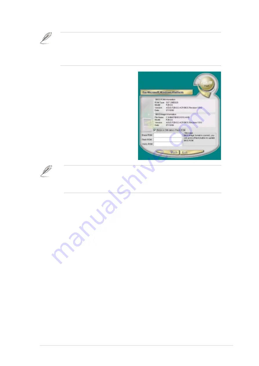
6. The next screen prompts you to

flash the original BIOS to update it
with the new boot logo. Click Flash
to update the BIOS.

7. When finished, click Exit, then reboot

your computer.

Your system boots with the new
boot logo.

Instead of starting from ASUS Update, you may also launch ASUS MyLogo2
directly from the Windows Start menu to change your BIOS boot logo. After you
have modified the BIOS file with the new logo, use the ASUS Update utility to
upload the new BIOS.

MyLogo2 may not support too complex images. If you encounter any problems on
complex images, try using a simpler image. You may also use a photo editing
software to shink the complex image, lay it over a one-color 640x480 pixel
background, and save the image with the background. When you use the image,
it will appear smaller and centered on the screen.

Содержание Motherboard P4PE BP

Страница 1: ...Motherboard P4PE BP User Guide ...

Страница 2: ... PARTICULAR PURPOSE IN NO EVENT SHALL ASUS ITS DIRECTORS OFFICERS EMPLOYEES OR AGENTS BE LIABLE FOR ANY INDIRECT SPECIAL INCIDENTAL OR CONSEQUENTIAL DAMAGES INCLUDING DAMAGES FOR LOSS OF PROFITS LOSS OF BUSINESS LOSS OF USE OR DATA INTERRUPTION OF BUSINESS AND THE LIKE EVEN IF ASUS HAS BEEN ADVISED OF THE POSSIBILITY OF SUCH DAMAGES ARISING FROM ANY DEFECT OR ERROR IN THIS MANUAL OR PRODUCT SPECIF...

Страница 3: ...1 7 2 Screw holes 1 10 1 8 Central Processing Unit CPU 1 11 1 8 1 Overview 1 11 1 8 2 Installing the CPU 1 12 1 9 System memory 1 13 1 9 1 Memory configurations 1 14 1 10 Expansion slots 1 14 1 10 1 Standard interrupt assignments 1 15 1 10 2 IRQ assignments for this motherboard 1 15 1 11 Jumpers 1 16 1 12 Connectors 1 18 Chapter 2 BIOS information 2 1 Managing and updating your BIOS 2 2 2 1 1 Usin...

Страница 4: ...Control 2 26 2 5 2 Hardware Monitor 2 27 2 6 Boot Menu 2 29 2 7 Exit Menu 2 31 Chapter 3 Software support 3 1 Install an operating system 3 2 3 2 Support CD information 3 2 3 2 1 Running the support CD 3 2 3 2 2 Drivers menu 3 3 3 2 3 Utilities menu 3 3 3 2 4 ASUS Contact Information 3 4 3 3 Software information 3 5 3 3 1 Multi channel audio feature 3 5 3 3 2 ASUS Instant Music 3 8 3 3 3 ASUS USB ...

Страница 5: ... harmful interference to radio or television reception which can be determined by turning the equipment off and on the user is encouraged to try to correct the interference by one or more of the following measures Reorient or relocate the receiving antenna Increase the separation between the equipment and receiver Connect the equipment to an outlet on a circuit different from that to which the rec...

Страница 6: ...your area If you are not sure about the voltage of the electrical outlet you are using contact your local power company If the power supply is broken do not try to fix it by yourself Contact a qualified service technician or your retailer Operation safety Before installing the motherboard and adding devices on it carefully read all the manuals that came with the package Before using the product ma...

Страница 7: ...d software products The ASUS websites are listed in the ASUS Contact Information on page viii 2 Optional Documentation Your product package may include optional documentation such as warranty flyers that may have been added by your dealer These documents are not part of the standard package WARNING Information to prevent injury to yourself when trying to complete a task CAUTION Information to prev...

Страница 8: ...IONAL America Address 6737 Mowry Avenue Mowry Business Center Building 2 Newark CA 94560 USA General Fax 1 510 608 4555 General Email tmd1 asus com Technical Support Support Fax 1 510 608 4555 General Support 1 502 933 8713 Web Site www asus com Support Email tsd asus com ASUS COMPUTER GmbH Germany and Austria Address Harkortstr 25 40880 Ratingen BRD Germany General Fax 49 2102 442066 General Emai...

Страница 9: ...upports PC2700 PC2100 FSB533 or PC2100 PC1600 FSB400 unbuffered non ECC DDR DIMMs 1 x AGP 4X 1 5V only 6 x PCI includes one ASUS BlueMagic PCI slot 2 x UltraDMA 100 66 33 connectors ADI AD1980 6 channel audio CODEC BROADCOM BCM4401 Fast Ethernet controller ASUS JumperFree mode ASUS EZ Plug ASUS MyLogo2 ASUS Q Fan ASUS EZ Flash ASUS Instant Music ASUS POST Reporter Power Loss Restart SFS Stepless F...

Страница 10: ... Chassis intrusion SMBus and SIR connectors GAME MIDI connector optional S PDIF Out connector optional CD AUX Modem audio connectors optional Front panel audio connector optional 4Mb Flash ROM Award BIOS TCAV PnP DMI2 0 WfM2 0 SM BIOS2 3 CrashFree BIOS Multi language BIOS ASUS EZ Flash ASUS MyLogo2 ASUS Instant Music PCI 2 2 USB 2 0 WfM 2 0 DMI 2 0 WOL WOR by PME chassis intrusion SMBus ATX form f...

Страница 11: ...1 This chapter describes the features of the P4PE BP motherboard It includes brief descriptions of the motherboard components and illustrations of the layout jumper settings and connectors Product introduction ...

Страница 12: ...nel audio features the P4PE BP is your perfect vehicle to get ahead in the world of power computing Before you start installing the motherboard and hardware devices on it check the items in your package with the list below 1 2 Package contents Check your P4PE BP package for the following items ASUS P4PE BP motherboard ATX form factor 12 in x 9 in 30 5 cm x 22 9 cm ASUS P4PE BP series support CD AS...

Страница 13: ... information USB Flash Disk This 32MB removable flash disk allows you to mobilize your data so easily Supporting a USB interface in a handy light packaging the USB Flash Disk makes copying and transferring files more convenient than ever See page 3 10 InterVideo WinDVD Suite Experience the world of multimedia with WinDVD Suite WinDVD 4 the most popular DVD player with 5 1 channel audio WinDVD Crea...

Страница 14: ...or 7 Floppy disk connector 8 IDE connectors 9 South Bridge controller 10 Speech controller 11 Flash ROM 12 Standby power LED 13 ASUS ASIC 14 Super I O controller 15 PCI slots 16 Audio CODEC optional 17 LAN controller optional 18 AGP warning LED 19 AGP slot 20 PS 2 mouse port 21 Parallel port 22 RJ 45 port optional 23 Line In jack optional 24 Line Out jack optional 25 Microphone jack optional 26 US...

Страница 15: ...ASUS P4PE BP motherboard user guide 1 5 3 4 19 1 18 6 7 12 11 15 2 5 8 13 14 16 9 17 10 20 21 29 28 27 26 23 24 25 22 ...

Страница 16: ... of the connector is slotted to prevent incorrect insertion of the floppy disk cable IDE connectors These dual channel bus master IDE connectors support Ultra DMA 100 66 PIO Modes 3 4 IDE devices Both the primary blue and secondary black connectors are slotted to prevent incorrect insertion of the IDE ribbon cable South bridge controller The fourth generation Intel I O Controller Hub ICH4 is a sub...

Страница 17: ...X mode graphics cards for 3D graphical applications PS 2 mouse port This green 6 pin connector is for a PS 2 mouse Parallel port This 25 pin port connects a parallel printer a scanner or other devices RJ 45 port This port allows connection to a Local Area Network LAN through a network hub on LAN models only Line In jack This Line In light blue jack connects a tape player or other audio sources In ...

Страница 18: ...1 GAME1 CLRTC SPDIF1 KBPWR1 CHASSIS1 USB_56 Super I O 4Mbit Firmware Hub ASUS ASIC with Hardware Monitor DDR DIMM1 64 72 bit 184 pin module 0 1 PS 2KBMS T Mouse B Keyboard DDR DIMM2 64 72 bit 184 pin module 2 3 DDR DIMM3 64 72 bit 184 pin module 4 5 Below Mic In Center Line Out Top Line In CPU_FAN1 SEC_IDE CHA_FAN1 PWR_FAN1 PCI2 PCI3 PCI4 PCI5 BlueMagic PCI Slot CR2032 3V Lithium Cell CMOS Power A...

Страница 19: ...omponent ensure that the ATX power supply is switched off or the power cord is detached from the power supply Failure to do so may cause severe damage to the motherboard peripherals and or components When lit the green LED SB_PWR1 indicates that the system is ON in sleep mode or in soft off mode a reminder that you should shut down the system and unplug the power cable before removing or plugging ...

Страница 20: ...1 Placement direction When installing the motherboard make sure that you place it into the chassis in the correct orientation The edge with external ports goes to the rear part of the chassis as indicated in the image below 1 7 2 Screw holes Place seven 7 screws into the holes indicated by circles to secure the motherboard to the chassis Make sure to unplug the power cord before installing or remo...

Страница 21: ...g Technology 2 Hyper Threading Technology is supported under Windows XP and Linux 2 4 x kernel and later versions only Under Linux use the Hyper Threading compliler to compile the code If you are using any other operating systems disable the Hyper Threading Techonology item in BIOS to ensure system stability and performance 3 It is recommended that you install WinXP Service Pack 1 4 Make sure to e...

Страница 22: ... its marked corner matches the base of the socket lever 4 Carefully insert the CPU into the socket until it fits in place The CPU fits only in one correct orientation DO NOT force the CPU into the socket to prevent bending the pins and damaging the CPU 5 When the CPU is in place push down the socket lever to secure the CPU The lever clicks on the side tab to indicate that it is locked Socket Lever...

Страница 23: ...DIMM Type Memory Frequency 533 MHz PC2700 333 MHz PC2100 266 MHz 400 MHz PC2100 266 MHz PC1600 200 MHz Make sure to unplug the power supply before adding or removing DIMMs or other system components Failure to do so may cause severe damage to both the motherboard and the components P4PE BP P4PE BP 184 Pin DDR DIMM Sockets 80 Pins 104 Pins Follow these steps to install a DIMM 1 Unlock a DIMM socket...

Страница 24: ...e expansion card according to the card documentation 1 9 1 Memory configurations You may install any DDR DIMMs with 64MB 128MB 256MB 512MB and 1GB densities into the DIMM sockets 1 DDR DIMM sockets 2 and 3 share the same rows so if you install a double sided DIMM into DIMM2 socket you must leave DIMM3 socket empty 2 You may install single sided DIMMs into DIMM2 and DIMM3 sockets at the same time b...

Страница 25: ... 9 Primary IDE Channel 15 10 Secondary IDE Channel These IRQs are usually available for ISA or PCI devices When using PCI cards on shared slots ensure that the drivers support Share IRQ or that the cards do not need IRQ assignments Otherwise conflicts will arise between the two PCI groups making the system unstable and the card inoperable 1 10 2 IRQ assignments for this motherboard A B C D E F G H...

Страница 26: ...eyboard the default is the Space Bar This feature requires an ATX power supply that can supply at least 1A on the 5VSB lead and a corresponding setting in the BIOS 2 Wireless PCI and USB settings 3 pin WPCI_USB These jumpers are reserved DO NOT change the default settings P4PE BP P4PE BP WPCI_USB Setting WPCI_USB Wireless PCI_USB Default 3 5 4 6 1 3 2 4 Original PCI reserved pin P4PE BP P4PE BP Ke...

Страница 27: ...pins 2 3 Keep the cap on pins 2 3 for about 5 10 seconds then move the cap back to pins 1 2 3 Plug the power cord and turn ON the computer 4 Hold down the Del key during the boot process and enter BIOS setup to re enter data Except when clearing the RTC RAM never remove the cap on CLRTC1 jumper default position Removing the cap will cause system boot failure You do not need to clear the RTC when t...

Страница 28: ...s LED to light up 2 Floppy disk drive connector 34 1 pin FLOPPY This connector supports the provided floppy drive ribbon cable After connecting one end to the motherboard connect the other end to the floppy drive Pin 5 is removed to prevent incorrect insertion when using ribbon cables with pin 5 plug P4PE BP P4PE BP HD Activity LED TIP If the case mounted LED does not light up try reversing the 2 ...

Страница 29: ...upports specific device bootup If you have more than two UltraDMA 100 66 devices purchase another UltraDMA 100 66 cable You may configure two hard disks to be both master devices with two ribbon cables one for the primary IDE connector and another for the secondary IDE connector 1 Pin 20 on each IDE connector is removed to match the covered hole on the UltraDMA cable connector This prevents incorr...

Страница 30: ...rboard requires that you connect the 4 pin ATX 12V power plug to provide sufficient power to the CPU If you are using a standard ATX power supply that does not have the ATX 12V plug connect one 4 pin device power plug to the ASUS EZ Plug connector labeled EZ_PLUG1 Make sure that your ATX 12V power supply can provide 8A on the 12V lead and at least 1A on the 5 volt standby lead 5VSB The minimum rec...

Страница 31: ...assis Signal and Ground are shorted with a jumper cap If you wish to use the chassis intrusion detection feature remove the jumper cap from the pins 7 Infrared module connector 5 1 pin IR1 This connector supports an optional wireless transmitting and receiving infrared module This module mounts to a small opening on system chassis that support this feature You must also configure the UART2 Use As ...

Страница 32: ...may damage the motherboard components These are not jumpers DO NOT place jumper caps on the fan connectors P4PE BP P4PE BP 12 Volt Fan Connectors CPU_FAN1 PWR_FAN1 CHA_FAN1 GND Rotation 12V GND Rotation 12V GND Rotation 12V P4PE BP P4PE BP Game Connector GAME1 5V 5V J2B1 J2CX MIDI_OUT J2CY J2B2 MIDI_IN J1B1 J1CX GND GND J1CY J1B2 5V 1 9 GAME MIDI connector 16 1 pin GAME1 This connector supports a ...

Страница 33: ...is header The module has two USB 2 0 ports that support the next generation USB peripherals such as high resolution cameras scanners and printers You must install the driver before you can use the USB 2 0 capability P4PE BP AUX1 White P4PE BP Internal Audio Connectors MODEM1 Modem In Ground Modem Out Ground CD1 Black Right Audio Channel Left Audio Channel Ground Ground 11 Internal audio connectors...

Страница 34: ...E BP P4PE BP Front Panel Audio Connector FP_AUDIO1 BLINE_OUT_L MIC2 Line out_R Line out_L BLINE_OUT_R NC MICPWR 5VA AGND P4PE BP P4PE BP Digital Audio Connector SPDIF1 5V SPDIFOUT GND 13 Front panel audio connector 10 1 pin FP_AUDIO1 on audio models only This is an interface for the Intel front panel audio cable that allow convenient connection and control of audio devices By default the pins labe...

Страница 35: ...to a suspend mode or green mode where system activity is instantly decreased to save power and to expand the life of certain system components Attach the case mounted suspend switch to this 2 pin connector ATX Power Switch Soft Off Switch Lead 2 pin PWRBTN This connector connects a switch that controls the system power Pressing the power switch turns the system between ON and SLEEP or ON and SOFT ...

Страница 36: ...1 26 Chapter 1 Product introduction ...

Страница 37: ...Chapter 2 This chapter tells how to change system settings through the BIOS Setup menus Detailed descriptions of the BIOS parameters are also provided BIOS information ...

Страница 38: ...see ASUS contact information on page viii Save the file to a floppy disk 2 Reboot the computer 3 To use EZ Flash press Alt F2 during POST to display the following screen Write down the BIOS file name on a piece of paper You need to type the exact BIOS file name at the EZ Flash screen 4 Insert the disk that contains the new BIOS file into the floppy drive You will receive the error message WARNING ...

Страница 39: ...pe in the correct file name Press Enter 6 At the above prompt type Y to continue with the update process Pressing N exits the EZ Flash screen and reboots the system without updating the BIOS The following prompts appear if you typed Y 7 Press Y to update the main BIOS area BIOS Information in File BIOS Version P4PE BP Boot Block WARNING Continue to update the BIOS Y N _ DO NOT shutdown or reset th...

Страница 40: ... copy AUTOEXEC BAT and CONFIG SYS to the disk 2 Type COPY D AFLASH AFLASH EXE A assuming D is your CD ROM drive to copy AFLASH EXE to the boot disk you created BIOS setup must specify Floppy as the first item in the boot sequence 4 In DOS mode type A AFLASH Enter to run AFLASH If the word unknown appears after Flash Memory the memory chip is either not programmable or is not supported by the ACPI ...

Страница 41: ... boot floppy disk you created earlier 2 Boot from the floppy disk 3 At the A prompt type AFLASH and then press Enter 4 At the Main Menu type 2 then press Enter The Update BIOS Including Boot Block and ESCD screen appears 5 Type the filename of your new BIOS and the path for example A XXX XX XXX then press Enter To cancel this operation press Enter Update the BIOS only if you have problems with the...

Страница 42: ... When the programming is done the message Flashed Successfully appears 8 Follow the onscreen instructions to continue If you encounter problems while updating the new BIOS DO NOT turn off the system because this may cause boot problems Just repeat the process and if the problem persists load the original BIOS file you saved to the boot disk If the Flash Memory Writer utility is not able to success...

Страница 43: ...e CrashFree BIOS 2 auto recovery on this motherboard install a VGA card into one of the expansion slots before rebooting the computer On motherboards with onboard VGA you will not see the screen display when the BIOS crashes even if you reboot the computer To update the BIOS using the bootable support CD 1 Boot the computer using the support CD The support CD automatically detects if the BIOS is c...

Страница 44: ...h its test routines If you wish to enter Setup after POST restart the system by pressing Ctrl Alt Delete or by pressing the reset button on the system chassis You can also restart by turning the system off and then back on Do this last option only if the first two failed The Setup program is designed to make it as easy to use as possible It is a menu driven program which means you can scroll throu...

Страница 45: ... the highlighted field Home or PgUp Moves the cursor to the first field End or PgDn Moves the cursor to the last field F5 Resets the current screen to its Setup Defaults F10 Saves changes and exits Setup General help In addition to the Item Specific Help window the BIOS setup program also provides a General Help screen You may launch this screen from any menu by simply pressing F1 or the Alt H com...

Страница 46: ...nd sub menus If you accidentally make unwanted changes to any of the fields use the set default hot key F5 to load the Setup default values While moving around through the Setup program note that explanations appear in the Item Specific Help window located to the right of each menu This window displays the help text for the currently highlighted field System Time XX XX XX Sets the system to the ti...

Страница 47: ...in the Main menu The passwords control access to the BIOS during system startup Passwords are not case sensitive meaning passwords typed in either uppercase or lowercase letters are accepted The BIOS Setup program allows you to specify two different passwords a Supervisor password and a User password If you did not set a Supervisor password anyone can access the BIOS Setup program If you did the S...

Страница 48: ...formatted on an older system Setup may detect incorrect parameters In these cases select User Type HDD to manually enter the IDE hard disk drive parameters Refer to the next section for details Before attempting to configure a hard disk drive make sure you have the correct configuration information supplied by the drive manufacturer Incorrect settings may cause the system to fail to recognize the ...

Страница 49: ...Manual Cylinders This field configures the number of cylinders Refer to the drive documentation to determine the correct value To make changes to this field set the Type field to User Type HDD and the Translation Method field to Manual Head This field configures the number of read write heads Refer to the drive documentation to determine the correct value To make changes to this field set the Type...

Страница 50: ...ctors 8 Sectors 16 Sectors 32 Sectors Maximum SMART Monitoring Disabled This field allows you to enable or disable the S M A R T Self Monitoring Analysis and Reporting Technology system that utilizes internal hard disk drive monitoring technology This parameter is normally disabled because the resources used in the SMART monitoring feature may decrease system performance Configuration options Disa...

Страница 51: ...is field sets the time interval for displaying the first and second characters Configuration options 1 4 Sec 1 2 Sec 3 4 Sec 1 Sec 2 4 Advanced Menu CPU Speed Manual When the motherboard is set to JumperFree mode this field allows you to select the internal frequency of the CPU Select Manual if you want to make changes to the two subsequent fields Note that selecting a frequency higher than the CP...

Страница 52: ...uency may cause the system to be unstable CPU VCore Setting Auto The Manual setting allows you to manually select the core voltage supplied to the CPU see next item However it is recommended that you keep the default setting Auto to allow the system to automatically determine the appropriate CPU core voltage CPU VCore 1 500V When the CPU VCore Setting parameter above is set to Manual the CPU VCore...

Страница 53: ...up Configuration options Disabled Enabled PS 2 Mouse Function Control Auto The default setting Auto allows the system to detect a PS 2 mouse at startup If a mouse is detected the BIOS assigns IRQ12 to the PS 2 mouse Otherwise IRQ12 can be used for expansion cards When you set this field to Enabled BIOS reserves IRQ12 whether or not a PS 2 mouse is detected at startup Configuration options Enabled ...

Страница 54: ...e only when you set the SDRAM Configuration to User Defined SDRAM CAS Latency value depends on SDRAM SPD This item controls the latency between the SDRAM read command and the time the data actually becomes available Configuration options 2 5T 2T 1 5T SDRAM RAS to CAS Delay value depends on SDRAM SPD This item controls the latency between the DDR SDRAM active command and the read write command Conf...

Страница 55: ...ode the AGP interface only provides a peak data throughput of 266MB s even if you are using an AGP 4X card Configuration options 1X Mode 4X Mode Video Memory Cache Mode UC USWC uncacheable speculative write combining is a new cache technology for the video memory of the processor It can greatly improve the display speed by caching the display data You must set this to UC uncacheable if your displa...

Страница 56: ...writes to the floppy disk drive The default setting R W allows both reads and writes Configuration options R W Read Only Onboard Serial Port 1 3F8H IRQ4 Onboard Serial Port 2 2F8H IRQ3 These fields allow you to set the addresses for the onboard serial connectors Serial Port 1 and Serial Port 2 must have different addresses Configuration options 3F8H IRQ4 2F8H IRQ3 3E8H IRQ4 2E8H IRQ10 Disabled UAR...

Страница 57: ...me port Configuration options Disabled 200H 207H 208H 20FH Onboard MIDI I O Disabled This field sets the I O address for the MIDI I O port Configuration options Disabled 330H 331H 300H 301H Speech POST Reporter Enabled This field enables or disables the ASUS POST Reporter feature When set to Enabled the items Report IDE Error Report System Checking and Report System Booting appear to allow customi...

Страница 58: ... options Disabled Enabled PCI Latency Timer 32 Leave this field to the default setting 32 for best performance and stability USB 1 1 Controllers 3 Controllers This field allows you to select the number of USB 1 1 controllers that you wish to activate Configuration options Disabled 3 Controllers USB 2 0 Controller Enabled This field allows you to enable or disable the onboard USB 2 0 controller Set...

Страница 59: ...es that you are using the ISA Configuration Utility ICU and that this particular IRQ is NOT required by a legacy ISA card Set the IRQ field to Yes if you install a legacy ISA card that requires a unique IRQ and you are NOT using ICU Configuration options No ICU Yes Onboard LAN Boot ROM Disabled appears on LAN models only This field allows you to enable or disable the option ROM in the onboard LAN ...

Страница 60: ...ally puts the system into suspend mode after a brief period of system inactivity Min Saving allows the least power saving as the system enters suspend mode only after a long period of inactivity Configuration options User Defined Disabled Min Saving Max Saving You should install the Advanced Power Management APM utility to keep the system time updated even when the computer enters suspend mode In ...

Страница 61: ...y to provide more than 720mA current Configuration options Disabled Enabled Suspend Mode Disabled Sets the time period before the system goes into suspend mode Configuration options Disabled 1 2 Min 2 3 Min 4 5 min 8 9 Min 20 Min 30 Min 40 Min 1 hour PWR Button 4 Secs Soft Off When set to Soft off the ATX switch can be used as a normal system power off button when pressed for less than 4 seconds S...

Страница 62: ...t be made on the first try Turning an external modem off and then back on while the computer is off causes an initialization string that turns the system power on Power Up On PCI Device Disabled When set to Enabled this parameter allows you to turn on the system through a PCI LAN or modem card This feature requires an ATX power supply that provides at least 1A on the 5VSB lead Configuration option...

Страница 63: ...a two pin thermal sensor cable connect this cable to the TRPWR1 connector on the motherboard to allow BIOS to auto detect the power supply temperature see page 2 24 for the location of the TRPWR1 connector The POWER temperature item shows the detected value if you have the appropriate power supply Select Ignore to disable the power temperature auto detect function Q Fan Control Disabled This item ...

Страница 64: ...e Q Fan Control item is set to Enabled Configuration options 1 Sec 2 Sec 2 Sec 4 Sec 3 Sec 6 Sec 4 Sec 8 Sec CPU Fan Speed xxxxRPM or N A Chassis Fan Speed xxxxRPM or N A Power Fan Speed xxxxRPM or N A The onboard hardware monitor automatically detects and displays the CPU chassis and power fan speeds in rotations per minute RPM If any of the fans is not connected to the motherboard the specific f...

Страница 65: ...ive This field allows you to select which IDE hard disk drive to use in the boot sequence Pressing Enter will show the product IDs of all connected IDE hard disk drives ATAPI CD ROM This field allows you to select which ATAPI CD ROM drive to use in the boot sequence Pressing Enter will show the product IDs of all your connected ATAPI CD ROM drives Other Boot Device Select INT18 Device Network Conf...

Страница 66: ...iguration options Disabled Enabled Quick Power On Self Test Enabled This field speeds up the Power On Self Test POST routine by skipping retesting a second third and fourth time Configuration options Disabled Enabled Boot Up Floppy Seek Enabled When enabled the BIOS will seek the floppy disk drive to determine whether the drive has 40 or 80 tracks Configuration options Disabled Enabled Full Screen...

Страница 67: ...ne of the options from this menu or F10 from the legend bar to exit If you attempt to exit the Setup program without saving your changes the program prompts you with a message asking if you want to save your changes before exiting Pressing Enter saves the changes while exiting Exit Discard Changes Select this option only if you do not want to save the changes that you made to the Setup program If ...

Страница 68: ...ing this option a confirmation appears Select Yes to discard any changes and load the previously saved values Save Changes This option saves your selections without exiting the Setup program You can then return to other menus and make further changes After you select this option a confirmation window appears Select Yes to save changes to the non volatile RAM ...

Страница 69: ...Chapter 3 This chapter describes the contents of the support CD that comes with the motherboard package Software support ...

Страница 70: ...t CD that came with the motherboard contains useful software and several utility drivers that enhance the motherboard features 3 2 1 Running the support CD To begin using the support CD simply insert the CD into your CD ROM drive The CD automatically displays the Drivers menu if Autorun is enabled in your computer The contents of the support CD are subject to change at any time without notice Visi...

Страница 71: ...help or readme file that came with the utility Intel Application Accelerator Driver This item installs the Intel Application Accelerator for Microsoft Windows 98SE ME NT4 0 2000 This program is designed to improve performance of the storage sub system and overall system performace Install the INF Driver before installing the Intel Application Accelerator SoundMAX Audio Driver and Application This ...

Страница 72: ...PC CILLIN 2002 This item installs the PC cillin 2002 anti virus program View the PC cillin online help for detailed information Adobe Acrobat Reader This item installs the Adobe Acrobat Reader V5 0 The Acrobat Reader software is for viewing files saved in Portable Document Format PDF ASUS Screen Saver This item installs the ASUS screen saver E Color 3Deep This item installs the 3Deep software 3Dee...

Страница 73: ...the taskbar double click on the SoundMAX Digital Integrated Audio icon to display the SoundMAX Control Panel 2 The Listening Environment screen allows you to set to multi channel speakers enable or disable the Virtual Theater Surround and select Acoustic Environments and Virtual Ear Sound MAX Digital Integrated Audio icon 3 The default setting is Stereo Speakers 2 channel To set to a 6 channel spe...

Страница 74: ... audio path The Play Test Noise button becomes Stop Playing button Click this button at any time to stop playing 9 Click the Close button when done 10 The MIDI Music Synthesizer screen allows you to select a setting for the MIDI 11 Click the arrow under Synthesizer Default Set to display a list of options Choose your desired setting 12 Click Apply then click OK when done Audio path indicator ...

Страница 75: ...appears To achieve 6 channel audio capability when playing DVDs check the boxes opposite AC3 SPDIF and PCM SPDIF Click Close You do not need to do step 2 if you did not install an S PDIF module Rear panel audio ports function variation The functions of the Line Out lime Line In blue and Mic pink ports on the rear panel change when you select the 4 channel or 6 channel audio configuration as shown ...

Страница 76: ...sic mode the system wake up features LAN keyboard mouse USB are deactivated In this case power up the system using the power switch 3 If the system lost connection or did not detect any optical drive the Instant Music feature turns OFF disabled automatically A beep indicates this condition 5 Save your changes and exit BIOS Setup If you have only one optical drive either CD ROM DVD ROM or CD RW ins...

Страница 77: ...ic function keys Set 2 As an alternative you may also use another set of keys on the motherboard as Instant Music function keys These keys are indicated by red numbers in the motherboard illustration below The functions are defined in the illustration on the right These labels all come with your motherboard package Esc F1 F2 F3 F4 F5 F6 F7 F8 3 Connect speakers or a headphone to the Line Out lime ...

Страница 78: ...3 3 3 ASUS USB Flash Disk If you are using Windows 98 or Windows ME you need to install the USB Flash Disk driver from the support CD For detailed information using the ASUS USB Flash Disk refer to the manual from the folder ASUS USB Flash Disk Manual in the support CD You do not need to install the driver if you are using other operating systems To install the ASUS USB Flash Disk driver 1 Insert ...

Страница 79: ...the program Launch the program either from the Winbond Voice Editor icon on your desktop or from the Windows Start menu Programs Winbond Voice Editor Voice Editor The Winbond Voice Editor screen appears Playing the default wave files To play the default wave files simply click on a POST event on the left side of the screen then click the Play button The default language setting is English To avoid...

Страница 80: ...r language is not in the selection or if you wish to record your own POST messages to replace the pre installed wave files you may easily do so Follow these steps to customize your POST messages 1 Launch the Voice Editor and take note of the list of POST events on the leftmost column of the screen 2 Prepare your message for each event The total compressed size for all the wave files must not excee...

Страница 81: ... FDD Detection IDE HDD Detection etc 7 Click a POST event on the Voice Editor screen then on the Edit button The Event Sound Editor window appears 8 Locate and select your wave file for the event then click on the arrow opposite Voice1 The file you selected appears on the space next to it 9 Click OK to return to the Voice Editor screen 10 Do steps 7 to 9 for the other events 11 When done click the...

Страница 82: ...y disk Click Next Before using ASUS MyLogo2 feature use the AFLASH utility to make a copy of your original BIOS file or obtain the latest BIOS version from the ASUS website Make sure that the BIOS item Full Screen Logo is set to Enabled is you wish to use ASUS MyLogo2 See page 4 35 Follow these steps to use ASUS MyLogo2 4 From the selection that appears choose a logo image Click Next 5 When you cl...

Страница 83: ...ogo2 directly from the Windows Start menu to change your BIOS boot logo After you have modified the BIOS file with the new logo use the ASUS Update utility to upload the new BIOS MyLogo2 may not support too complex images If you encounter any problems on complex images try using a simpler image You may also use a photo editing software to shink the complex image lay it over a one color 640x480 pix...

Страница 84: ...3 16 Chapter 3 Software support ...

Отзывы: