background image

ASUS PSCH-L motherboard

4-7

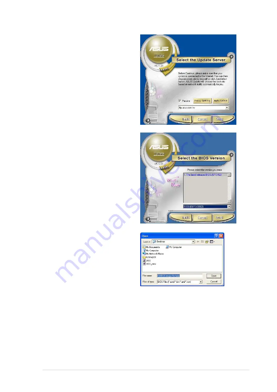
4. From the FTP site, select the

BIOS version that you wish to
download. Click Next.

5. Follow the instructions on the

succeeding screens to complete
the update process.

If you selected the option to update
the BIOS from a file, a window
prompts you to locate the file.
Select the file, click Save, then
follow the screen instructions to
complete the update process.

3. If you selected updating/

downloading from the Internet,
select the ASUS FTP site
nearest you to avoid network
traffic, or choose Auto Select.
Click Next.

Содержание Motherboard AP130-E1

Страница 1: ...Motherboard PSCH L User Guide ...

Страница 2: ... PARTICULAR PURPOSE IN NO EVENT SHALL ASUS ITS DIRECTORS OFFICERS EMPLOYEES OR AGENTS BE LIABLE FOR ANY INDIRECT SPECIAL INCIDENTAL OR CONSEQUENTIAL DAMAGES INCLUDING DAMAGES FOR LOSS OF PROFITS LOSS OF BUSINESS LOSS OF USE OR DATA INTERRUPTION OF BUSINESS AND THE LIKE EVEN IF ASUS HAS BEEN ADVISED OF THE POSSIBILITY OF SUCH DAMAGES ARISING FROM ANY DEFECT OR ERROR IN THIS MANUAL OR PRODUCT SPECIF...

Страница 3: ...ction 2 2 2 2 2 Screw holes 2 2 2 2 3 Motherboard layout 2 3 2 2 4 Layout Contents 2 4 2 3 Central Processing Unit CPU 2 5 2 3 1 Overview 2 5 2 3 2 Installing the CPU 2 6 2 3 3 Installing the heatsink and fan 2 8 2 3 4 Connecting the CPU fan cable 2 10 2 4 System memory 2 11 2 4 1 Overview 2 11 2 4 2 Memory configurations 2 11 2 4 3 Installing a DIMM 2 13 2 4 4 Removing a DIMM 2 13 2 5 Expansion s...

Страница 4: ... 3 Navigation keys 4 9 4 2 4 Menu items 4 10 4 2 5 Sub menu items 4 10 4 2 6 Configuration fields 4 10 4 2 7 Pop up window 4 10 4 2 8 Scroll bar 4 10 4 2 9 General help 4 10 4 3 Main menu 4 11 4 3 1 System Information 4 11 4 3 2 System Time 4 12 4 3 3 System Date 4 12 4 3 4 Floppy A 4 12 4 3 5 Primary and Secondary IDE Master Slave Third IDE SATA Fourth IDE SATA 4 12 4 3 6 Boot Options 4 14 4 3 7 ...

Страница 5: ...otection 4 31 4 5 5 Diskette Write 4 31 4 5 6 Flash Write 4 31 4 5 7 System Load 4 32 4 5 8 Setup Prompt 4 32 4 6 Power menu 4 33 4 6 1 Power Failure Recovery 4 33 4 6 2 Resume On Ring 4 33 4 6 2 Resume On LAN 4 33 4 6 3 Resume On RTC Alarm 4 33 4 7 Exit menu 4 34 4 7 1 Save Changes and Exit 4 34 4 7 2 Load Previous Values and Exit 4 34 4 7 3 Load Previous Values 4 34 4 7 4 Load Optimal Defaults 4...

Страница 6: ...ause harmful interference to radio or television reception which can be determined by turning the equipment off and on the user is encouraged to try to correct the interference by one or more of the following measures Reorient or relocate the receiving antenna Increase the separation between the equipment and receiver Connect the equipment to an outlet on a circuit different from that to which the...

Страница 7: ...your area If you are not sure about the voltage of the electrical outlet you are using contact your local power company If the power supply is broken do not try to fix it by yourself Contact a qualified service technician or your retailer Operation safety Before installing the motherboard and adding devices on it carefully read all the manuals that came with the package Before using the product ma...

Страница 8: ...e installation This chapter lists the hardware setup procedures that you have to perform when installing system components It includes description of the switches jumpers and connectors on the motherboard Chapter 3 Powering up This chapter describes the power up sequence and gives information on the BIOS beep codes Chapter 4 BIOS setup This chapter tells how to change system settings through the B...

Страница 9: ...rdware and software products Refer to the ASUS contact information 2 Optional Documentation Your product package may include optional documentation such as warranty flyers that may have been added by your dealer These documents are not part of the standard package WARNING Information to prevent injury to yourself when trying to complete a task CAUTION Information to prevent damage to the component...

Страница 10: ...66MHz PCI 3 x 5V 32 bit 33MHz PCI Supported by South Bridge 6300ESB ICH 2 x UltraDMA100 connectors 2 x Serial ATA connectors Supported by Promise PDC20319 controller 4 x Serial ATA connectors RAID0 RAID1 RAID0 1 Multi RAID configurations Intel 82547GI Gigabit LAN controller ATI RAGE XL PCI based VGA controller 1 x Parallel port 1 x Serial port 1 x VGA port 1 x PS 2 keyboard port 1 x PS 2 mouse por...

Страница 11: ...ts Specifications are subject to change without notice WfM 2 0 DMI 2 0 WOL WOR by PME chassis intrusion ATX power supply with 4 pin 12V plug ATX form factor 12 in x 9 6 in 30 5 cm x 24 5 cm Device drivers Management software System utilities ASUS contact information ...

Страница 12: ...xii ...

Страница 13: ...Chapter 1 This chapter describes the features of the motherboard It includes brief explanations of the special attributes of the motherboard and the new technology it supports Product introduction ...

Страница 14: ...ASUS PSCH L motherboard Chapter summary 1 1 Welcome 1 1 1 2 Package contents 1 1 1 3 Special features 1 2 ...

Страница 15: ...mory with PC3200 2700 2100 DDR SDRAM onboard high resolution graphics Serial ATA support and USB 2 0 the PSCH L is your perfect vehicle to get ahead in the world of power computing Before you start installing the motherboard and hardware devices on it check the items in your package with the list below 1 2 Package contents Check your PSCH L package for the following items If any of the above items...

Страница 16: ...rd supports the new Serial ATA technology through the SATA interfaces and the Intel 6300ESB ICH and Promise PDC20319 controllers onboard The SATA specification allows for thinner more flexible cables with lower pin count reduced voltage requirement and up to 150MB s data transfer rate Multi RAID solution The motherboard has the Promise PDC20319 controller to support multi RAID solution using Seria...

Страница 17: ...2 0 technology The motherboard implements the Universal Serial Bus USB 2 0 specification dramatically increasing the connection speed from the 12 Mbps bandwidth on USB 1 1 to a fast 480 Mbps on USB 2 0 USB 2 0 is backward compatible with USB 1 1 ...

Страница 18: ...1 4 Chapter 1 Product introduction ...

Страница 19: ... Hardware information This chapter describes the hardware setup procedures that you have to perform when installing system components It includes details on the switches jumpers and connectors on the motherboard ...

Страница 20: ... L motherboard Chapter summary 2 1 Before you proceed 2 1 2 2 Motherboard installation 2 2 2 3 Central Processing Unit CPU 2 5 2 4 System memory 2 11 2 5 Expansion slots 2 14 2 6 Jumpers 2 17 2 7 Connectors 2 19 ...

Страница 21: ...ching the ICs on them 4 Whenever you uninstall any component place it on a grounded antistatic pad or in the bag that came with the component 5 Before you install or remove any component ensure that the ATX power supply is switched off or the power cord is detached from the power supply Failure to do so may cause severe damage to the motherboard peripherals and or components When lighted the green...

Страница 22: ...rboard make sure that you place it into the chassis in the correct orientation The edge with external ports goes to the rear part of the chassis as indicated in the image below 2 2 2 Screw holes Place nine 9 screws into the holes indicated by circles to secure the motherboard to the chassis Make sure to unplug the power cord before installing or removing the motherboard Failure to do so may cause ...

Страница 23: ...t 184 pin module CR2032 3V Lithium Cell CMOS Power PRI_IDE KBPWR1 AUX FAN SYSTEM FAN USB34 SB_PWR1 Promise PDC20319 RAID Controller CHASS1 EXTSMB1 ATX_POWER SLOT_2 64 bit 66MHz 3V USB12 RJ 45 PS 2 T Mouse B Keyboard SLOT_1 32 bit 33MHz 5V COM1 PARALLEL PORT VGA SLOT_4 32 bit 33MHz 5V SLOT_5 32 bit 33MHz 5V SLOT_3 64 bit 66MHz 3V ATI RAGE XL VGA Controller COM2 Intel 82547 Gigabit Ethernet THERMAL_...

Страница 24: ... 2 21 4 Serial ATA connectors 7 pin SATA IDE3 SATA IDE4 2 22 5 Serial ATA RAID connectors 7 pin R SATA1 R SATA2 R SATA3 R SATA4 2 22 6 Chassis intrusion connector 4 1 pin CHASS1 2 23 7 Power supply thermal connector 2 pin THERMAL_AUX 2 23 8 CPU System and Auxiliary fan connectors 3 pin CPU FAN SYSTEM FAN AUX FAN 2 24 9 Serial port 2 connector 10 2 pin COM2 2 24 10 ATX power connectors 20 pin ATXPW...

Страница 25: ...ler to compile the code If you are using any other operating systems disable the Hyper Threading Techonology item in BIOS to ensure system stability and performance 3 It is recommended that you install WinXP Service Pack 1 4 Make sure to enable the Hyper Threading Technology item in BIOS before installing a supported operating system 5 For more information on Hyper Threading Technology visit www i...

Страница 26: ... to install a CPU 1 Locate the 478 pin ZIF socket on the motherboard 2 Unlock the socket by pressing the lever sideways then lift it up to a 90 100 angle Make sure that the socket lever is lifted up to 90 100 angle otherwise the CPU does not fit in completely Socket Lever 90 100 ...

Страница 27: ...efully insert the CPU into the socket until it fits in place The CPU fits only in one correct orientation DO NOT force the CPU into the socket to prevent bending the pins and damaging the CPU 5 When the CPU is in place push down the socket lever to secure the CPU The lever clicks on the side tab to indicate that it is locked Gold Mark ...

Страница 28: ...teps to install the CPU heatsink and fan 1 Place the heatsink on top of the installed CPU making sure that the heatsink fits properly on the retention module base When you buy a boxed Intel Pentium 4 Processor the package includes the heatsink fan and retention mechanism In case you buy a CPU separately make sure that you use only Intel certified heatsink and fan Your boxed Intel Pentium 4 Process...

Страница 29: ...e holes on each corner of the module base Keep the retention locks lifted upward while fitting the retention mechanism to the module base Make sure that the fan and retention mechanism assembly perfectly fits the heatsink and module base otherwise you cannot snap the hooks into the holes Retention Hole Retention Hook Snapped to the Retention Hole Retention Lock ...

Страница 30: ...to the connector on the motherboard labeled CPU_FAN 3 Push down the locks on the retention mechanism to secure the heatsink and fan to the module base When secure the retention locks should point to opposite directions Don t forget to connect the CPU fan connector Hardware monitoring errors may occur if you fail to plug this connector CPU Fan Connector CPU_FAN ...

Страница 31: ...mended configurations may cause memory sizing error or system boot failure Use any of the recommended configurations in Table 1 2 In dual channel configurations install only identical the same type and size DDR DIMM pairs for each channel 3 Always install DIMMs with the same CAS latency For optimum compatibility it is recommended that you obtain memory modules from the same vendor 4 Make sure that...

Страница 32: ...uency CPU FSB synchronization Obtain DDR DIMMs only from ASUS qualified vendors for better system performance Visit the ASUS website www asus com for the latest QVL Sockets Mode DIMM_0A DIMM_1A DIMM_0B DIMM_1B blue black blue black Single channel 1 Populated 2 Populated 3 Populated 4 Populated Dual channel 1 Populated Populated 2 Populated Populated 3 Populated Populated Populated Populated CPU FS...

Страница 33: ... socket 2 4 4 Removing a DIMM Follow these steps to remove a DIMM 3 Firmly insert the DIMM into the socket until the retaining clips snap back in place and the DIMM is properly seated Locked Retaining Clip 1 Simultaneously press the retaining clips outward to unlock the DIMM 2 Remove the DIMM from the socket Unlocked Retaining Clip DDR DIMM notch A DDR DIMM is keyed with a notch so that it fits in...

Страница 34: ...pposite the slot that you intend to use Keep the screw for later use 4 Align the card connector with the slot and press firmly until the card is completely seated on the slot 5 Secure the card to the chassis with the screw you removed earlier 6 Replace the system cover Make sure to unplug the power cord before adding or removing expansion cards Failure to do so may cause you physical injury and da...

Страница 35: ...r 7 15 Printer Port LPT1 8 3 System CMOS Real Time Clock 9 4 ACPI Mode when used 10 5 IRQ Holder for PCI Steering 11 6 IRQ Holder for PCI Steering 12 7 PS 2 Compatible Mouse Port 13 8 Numeric Data Processor 14 9 Primary IDE Channel 15 10 Secondary IDE Channel These IRQs are usually available for ISA or PCI devices A B C D E F G H PXIRQ0 PXIRQ1 PXIRQ2 PXIRQ3 PCI slot 1 shared shared shared shared P...

Страница 36: ...CI cards such as a LAN card SCSI card USB card and other cards that comply with PCI specifications When installing long PCI cards it is recommended that you install them in PCI slots 1 4 or 5 Long PCI cards installed in PCI slots 2 and 3 may interfere with the SATA connectors ...

Страница 37: ...on the keyboard the default is the Space Bar This feature requires an ATX power supply that can supply at least 1A on the 5VSB lead and a corresponding setting in the BIOS see section 4 5 1 Power Up Control PSCH L PSCH L Keyboard Power Setting KBPWR1 Default 5V 5VSB 1 2 2 3 2 RAID enable 3 pin RAID_EN This jumper allows you enable or disable the onboard RAID feature PSCH L PSCH L RAID Setting RAID...

Страница 38: ...ll battery To erase the RTC RAM 1 Turn OFF the computer and unplug the power cord 2 Move the jumper cap from pins 1 2 default to pins 2 3 Keep the cap on pins 2 3 for about 5 10 seconds then move the cap back to pins 1 2 3 Plug the power cord and turn ON the computer 4 Hold down the Del key during the boot process and enter BIOS setup to re enter data Except when clearing the RTC RAM never remove ...

Страница 39: ...ces 3 PS 2 keyboard port This purple connector is for a PS 2 keyboard 4 USB 2 0 ports 1 and 2 These two 4 pin Universal Serial Bus USB ports are available for connecting USB 2 0 devices 5 Serial port This 9 pin COM1 port is for serial devices 6 Video port This port is for a VGA monitor or other VGA compatible devices 7 RJ 45 port This port allows connection to a Local Area Network LAN through a ne...

Страница 40: ... insertion when using ribbon cables with pin 5 plug PSCH L PSCH L Floppy Disk Drive Connector NOTE Orient the red markings on the floppy ribbon cable to PIN 1 PIN 1 FLOPPY 2 SMBus connector 6 1 pin EXTSMB1 This connector allows you to connect SMBus System Management Bus devices Devices communicate with an SMBus host and or other SMBus devices using the SMBus interface PSCH L PSCH L SMBus Connector...

Страница 41: ...ve as a slave device by setting its jumper accordingly Refer to the hard disk documentation for the jumper settings BIOS supports specific device bootup You may configure two hard disks to be both master devices with two ribbon cables one for the primary IDE connector and another for the secondary IDE connector 1 Pin 20 on each IDE connector is removed to match the covered hole on the UltraDMA cab...

Страница 42: ...Through the onboard Promise PDC20319 RAID controller you may create a RAID0 RAID1 RAID0 1 or multi RAID configuration 1 If you wish to create a RAID set make sure that you have connected the SATA cable and installed Serial ATA devices You cannot enter the SATARaid utility and SATA BIOS setup during POST if there are no connected Serial ATA devices 2 The Promise PDC20319 RAID controller does not su...

Страница 43: ...nal to this lead to record a chassis intrusion event By default the pins labeled Chassis Signal and Ground are shorted with a jumper cap If you wish to use the chassis intrusion detection feature remove the jumper cap from the pins 7 Power supply thermal connector 2 pin THERMAL_AUX If your power supply has a thermal monitoring feature connect its thermal sensor cable to this connector PSCH L PSCH ...

Страница 44: ...rs Lack of sufficient air flow within the system may damage the motherboard components These are not jumpers DO NOT place jumper caps on the fan connectors 9 Serial port 2 connector 10 1 pin COM2 This connector accommodates a second serial port using an optional serial port bracket Connect the bracket cable to this connector then install the bracket into a slot opening at the back of the system ch...

Страница 45: ...ct the 4 pin ATX 12V power plug to provide sufficient power to the CPU 1 Do not forget to connect the 4 pin ATX 12V power plug Otherwise the system does not boot up 2 Make sure that your ATX 12V power supply can provide 8A on the 12V lead and at least 1A on the 5 volt standby lead 5VSB The minimum recommended wattage is 300W The system may become unstable or may not boot up if the power is inadequ...

Страница 46: ...als Connect an to this header The module has two USB 2 0 ports that support the next generation USB peripherals such as high resolution cameras scanners printers and mobile storage devices 12 System panel connector 20 pin PANEL This connector accommodates several system front panel functions PSCH L PSCH L System Panel Connector Requires an ATX power supply PLED Ground PWR 5VSB 5V Speaker Power LED...

Страница 47: ...n HD_LED This lead connects the HDD LED cable The read or write activities of the device connected to the any of IDE connectors cause the IDE LED to light up System Management Interrupt Lead 2 pin SMI This lead connects the case mounted suspend switch and allows you to manually place the system into a suspend mode or green mode where system activity is instantly decreased to save power and to expa...

Страница 48: ...2 28 Chapter 2 Hardware information ...

Страница 49: ...Chapter 3 Powering up This chapter describes the power up sequence and gives information on the BIOS beep codes ...

Страница 50: ...ASUS PSCH L motherboard Chapter summary 3 1 Starting up for the first time 3 1 3 2 Powering off the computer 3 2 ...

Страница 51: ... green standards or if it has a power standby feature the monitor LED may light up or switch between orange and green after the system LED turns on The system then runs the power on tests While the tests are running the BIOS beeps see BIOS beep codes table below or additional messages appear on the screen If you do not see anything within 30 seconds from the time you turned on the power the system...

Страница 52: ...If you are using Windows XP or Windows Server 2003 1 Click the Start button then select Turn Off Computer 2 Click the Turn Off button to shut down the computer 3 The power supply should turn off after Windows shuts down 3 2 2 Using the dual function power switch While the system is ON pressing the power switch for less than 4 seconds puts the system to sleep mode or to soft off mode depending on t...

Страница 53: ...Chapter 4 BIOS setup This chapter tells how to change system settings through the BIOS Setup menus Detailed descriptions of the BIOS parameters are also provided ...

Страница 54: ... PSCH L motherboard Chapter summary 4 1 Managing and updating your BIOS 4 1 4 2 BIOS Setup program 4 8 4 3 Main menu 4 11 4 4 Advanced menu 4 18 4 5 Security menu 4 30 4 6 Power menu 4 33 4 7 Exit menu 4 34 ...

Страница 55: ...website and download the latest BIOS file for this motherboard using the ASUS Update utility 4 1 1 Creating a bootable floppy disk 1 Do either one of the following to create a bootable floppy disk DOS environment Insert a 1 44 MB floppy disk into the drive At the DOS prompt type format A S then press Enter Windows 98SE ME 2000 XP environment a Insert a 1 44 MB floppy disk into the floppy disk driv...

Страница 56: ...e the BIOS using the AFUDOS EXE utility in DOS environment 1 Visit the ASUS website www asus com to download the latest BIOS file for your motherboard Save the BIOS file to a bootable floppy disk 2 Copy the AFUDOS EXE utility from the support CD to the bootable floppy disk that contains the BIOS file 3 Boot the system from the floppy disk 4 At the DOS prompt type the command line afudos i filename...

Страница 57: ...ttings to a floppy or hard disk The copy can be used as a backup in case the system BIOS fails or gets corrupted 1 At the DOS prompt type the command line afudos o filename where filename can be any user provided filename of not more than eight 8 alpha numeric characters for the main filename and three 3 alpha numeric characters for the extension name 2 Press Enter Main filename Extension name A a...

Страница 58: ...sk 1 Boot the system 2 When a corrupted BIOS is detected the following screen message appears Bad BIOS checksum Starting BIOS recovery Checking for floppy 1 Prepare the support CD that came with the motherboard or a floppy disk that contains the motherboard BIOS before proceeding with the BIOS update process 2 If you have saved a copy of the original motherboard BIOS to a bootable floppy disk you ...

Страница 59: ...e necessary files are found in the floppy disk the BIOS update process continues 4 When the BIOS update process is complete reboot the system Make sure that the BIOS file in the floppy disk is renamed as PSCHL ROM DO NOT shutdown or reset the system while updating the BIOS Doing so may cause system boot failure Bad BIOS checksum Starting BIOS recovery Checking for floppy Floppy not found Checking ...

Страница 60: ...available in the support CD that comes with the motherboard package ASUS Update requires an Internet connection either through a network or an Internet Service Provider ISP To install ASUS Update 1 Insert the support CD into the CD ROM drive The Drivers menu appears 2 Click the Utilities tab then click Install ASUS Update VX XX XX See page 5 3 for the Utilities menu screen 3 The ASUS Update utilit...

Страница 61: ...plete the update process If you selected the option to update the BIOS from a file a window prompts you to locate the file Select the file click Save then follow the screen instructions to complete the update process 3 If you selected updating downloading from the Internet select the ASUS FTP site nearest you to avoid network traffic or choose Auto Select Click Next ...

Страница 62: ...gram Press Del during the Power On Self Test POST to enter the Setup utility Otherwise POST continues with its test routines If you wish to enter Setup after POST restart the system by pressing Ctrl Alt Delete or by pressing the reset button on the system chassis You can also restart by turning the system off and then back on Do this last option only if the first two failed The Setup program is de...

Страница 63: ...d 4 2 3 Navigation keys At the bottom right corner of a menu screen are the navigation keys for that particular menu Use the navigation keys to select items in the menu and change the settings Some of the navigation keys differ from one screen to another System Overview System Information System Time 11 10 19 System Date Sat 02 14 2004 Floppy A 1 44M 3 1 2 Primary IDE Master Hard Disk Primary IDE ...

Страница 64: ...m 4 2 8 Scroll bar A scroll bar appears on the right side of a menu screen when there are items that do not fit on the screen Press Up Down arrow keys or PageUp PageDown keys to display the other items on the screen 4 2 9 General help At the top right corner of the menu screen is a brief description of the selected item Scroll bar Select Screen Select Item Change Option F1 General Help F10 Save an...

Страница 65: ...ew System Information System Time 11 10 19 System Date Sat 02 14 2004 Floppy A 1 44M 3 1 2 Primary IDE Master Hard Disk Primary IDE Slave CD ROM Secondary IDE Master Not Detected Secondary IDE Slave Not Detected Third IDE SATA Not Detected Fourth IDE SATA Not Detected Boot Options System Memory 256MB Use ENTER TAB or SHIFT TAB to select a field Use or to configure system time System Overview AMIBI...

Страница 66: ...DE device Select a device item then press Enter to display the IDE device information Primary IDE Master Device Hard Disk Vendor ST320413A Size 20 0GB LBA Mode Supported Block Mode 16 Sectors PIO Mode 4 Async DMA MultiWord DMA 2 Ultra DMA Ultra DMA 2 S M A R T Supported Type Auto LBA Large Mode Auto Block Multi sector Transfer Auto PIO Mode Auto DMA Mode Auto S M A R T Auto 32Bit Data Transfer Dis...

Страница 67: ...Auto Block Multi sector Transfer Auto Enables or disables data multi sectors transfers When set to Auto the data transfer from and to the device occurs multiple sectors at a time if the device supports multi sector transfer feature When set to Disabled the data transfer from and to the device occurs one sector at a time Configuration options Disabled Auto PIO Mode Auto Selects the PIO mode Configu...

Страница 68: ...ed Clear Screen Delay sec 5 Interrupt 19 Capture Disabled Memory Test Enabled Boot Menu Enabled Allows BIOS to skip certain tests while booting This will decrease the time needed to boot the system Boot Settings Configuration Quick Boot Disabled Enabling this item allows the BIOS to skip some power on self tests POST while booting to decrease the time needed to boot the system When set to Disabled...

Страница 69: ...e system continues to boot or attempts to boot even if a boot error occurs Configuration options Disabled Enabled Clear Screen Delay sec 5 Allows you to set the delay time in seconds before clearing the screen to boot The value zero 0 means no delay Interrupt 19 Capture Disabled When set to Enabled this function allows the option ROMs to trap Interrupt 19 Configuration options Disabled Enabled Mem...

Страница 70: ...ce PM ST320413A 3rd Boot Device PS ASUS CD S340 Specifies the boot sequence from the available devices A device enclosed in parenthesis has been disabled in the corresponding type menu Hard Disk Drives Hard Disk Drives 1st Drive PM ST320413A 2nd Drive N A 3rd Drive N A 4th Drive N A Specifies the boot sequence from the available devices 1st 4th Drive These items specify the boot priority sequence ...

Страница 71: ...ms that appear on the screen depends on the the number of devices installed in the system Configuration options xxxxx Drive Disabled Removable Drives Removable Drives 1st Drive 1st FLOPPY DRIVE 2nd Drive N A 3rd Drive N A 4th Drive N A Specifies the boot sequence from the available devices 4 3 7 System Memory Displays the auto detected system memory ...

Страница 72: ...gure advanced CPU settings Ratio Status Locked Ratio Actual Value 18 Ratio CMOS Setting 4 L3 Cache Enabled Fast String Operation Enabled Compatible FPU Code Disabled Split Lock Operation Enabled Adjacent Sector Prefetch Enabled Hyper Threading Function Enabled MPS Revision 1 4 CPU Mismatch Detection Enabled CPU Clock Throttling Delay None Controls caching of L3 cache Advanced Settings CPU Configur...

Страница 73: ...ture Configuration options Disabled Enabled Adjacent Sector Prefetch Enabled Allows you to enable or disable the adjacent sector prefetch feature Configuration options Disabled Enabled Hyper Threading Function Disabled Allows you to enable or disable the CPU Hyper Threading Technology feature Configuration options Disabled Enabled MPS Revision 1 4 Configuration options 1 1 1 4 CPU Mismatch Detecti...

Страница 74: ...ode ECC DRAM Frequency Auto Allows you to select a specific DRAM frequency Select Auto for automatic adjustment of the DRAM operating frequency Configuration options 266 MHz 333 MHz 400 MHz Auto Configure DRAM timing by SPD Enabled When set to Enabled the DRAM SPD Serial Presence Detect function automatically configures the DRAM clock timing Configuration options Disabled Enabled DRAM Integrity Mo...

Страница 75: ...roller Enabled Allows you to enable or disable the onboard floppy disk controller Configuration options Disabled Enabled Serial Port1 Address 3F8 IRQ4 Allows you to select the Serial Port1 base address Configuration options Disabled 3F8 IRQ4 3E8 IRQ4 2E8 IRQ3 Serial Port2 Address 2F8 IRQ3 Allows you to select the Serial Port2 base address Configuration options Disabled 2F8 IRQ3 3E8 IRQ4 2E8 IRQ3 P...

Страница 76: ...item then press Enter if you wish to configure the item IDE Configuration IDE Channel Selection Both S ATA Running Enhanced Mode Yes Configure S ATA as RAID No IDE Detect Time out Sec 35 ATA PI 80Pin Cable Detection Host Device Allows BIOS to enable or disable the floppy drive controller IDE Channel Selection Both Allows you to select the IDE channel that you wish to enable Configuration options D...

Страница 77: ...figuration Module Version 2 23 2 7 4 USB Devices Enabled None USB Function All USB Ports Legacy USB Port Enabled USB 2 0 Controller Enabled USB 2 0 Controller Mode HiSpeed Enables USB host controllers USB Function All USB Ports Allows you to set the number of USB ports to activate Configuration options Disabled 2 USB Ports All USB Ports Legacy USB Support Enabled Allows you to enable or disable su...

Страница 78: ...Advanced Configuration and Power Interface settings Select an item then press Enter to display the configuration options For the second item a sub menu appears when you press Enter ACPI Settings ACPI Aware O S Yes Advanced ACPI Configuration Enable Disable ACPI support for the operating system ENABLE If OS supports ACPI DISABLE If OS does not support ACPI ACPI Aware O S Yes Allows you to enable or...

Страница 79: ...ions No Yes ACPI APIC Support Enabled Allows you to enable or disable the inclusion of ACPI APIC table pointer to RSDT pointer list Configuration options Disabled Enabled APIC ACPI SCI IRQ Disabled Allows you to enable or disable the APIC ACPI SCI interrupt Configuration options Disabled Enabled BIOS AML ACPI Table Enabled Allows you to enable or disable the inclusion of the BIOS AML exchange poin...

Страница 80: ...ter Enabled Latency Timer Default NO Lets the BIOS configure all the devices in the system YES Lets the operating system configure Plug and Play PnP devices not required for boot if your system has a Plug and Play operating system PCI Slot 1 Configuration Option ROM Scan Enabled Bus Master Enabled Latency Timer Default PCI Slot 2 Configuration Option ROM Scan Enabled Bus Master Enabled Latency Tim...

Страница 81: ...led Enabled Option ROM Scan Allows you to enable or disable the initialization of the expansion ROM Configuration options Disabled Enabled Bus Master Allows you to enable or disable the selected device as a PCI bus master Configuration options Disabled Enabled Promise RAID Device Allows you to enable or disable the PCI device Configuration options Disabled Enabled Option ROM Scan Allows you to ena...

Страница 82: ...Allows you to enable or disable the System Health Configuration feature When this feature is enabled the items in the menu displays the auto detected fan speeds system temperatures and output voltages When disabled the items show N A Configuration options Disabled Enabled 4 4 8 Hardware Health Configuration The items in this menu allow you to configure and monitor the hardware health items Hardwar...

Страница 83: ...SCH L motherboard 4 29 4 4 9 Remote Access Configuration The item in this menu allows you to configure the remote access type and parameters Configure Remote Access type and parameters Remote Access Disabled ...

Страница 84: ...tem Password Select this item to set or change the supervisor password The Setup Password item on top of the screen shows the default Not Installed After you have set a password this item shows Installed To set a Setup Password 1 Select the Set Setup Password item and press Enter 2 On the password box that appears type a password composed of letters and or numbers then press Enter Your password sh...

Страница 85: ...5 3 System Password Mode System When set to System BIOS requires you to enter the System Password to continue the boot process When set to Keyboard the system is secured at boot to prevent tampering during network operation Configuration options System Keyboard 4 5 4 Boot Sector Virus Protection Disabled Allows you to enable or disable the boot sector virus protection Configuration options Disable...

Страница 86: ...m a floppy disk or an ATAPI CD ROM Set to Diskette CDROM Lock to prevent booting from these drives Configuration options Standard Diskette CDROM Lock 4 5 8 Setup Prompt Enabled When set to Enabled displays the message Press DEL to run Setup during POST Configuration options Disabled Enabled ...

Страница 87: ...ystem goes on after an AC power loss When set to Last State the system goes into either off or on state whatever was the system state before the AC power loss Configuration options Power Off Power On Last State 4 6 2 Resume On Ring Disabled Allows you to enable or disable RI to generate a wake event Configuration options Disabled Enabled 4 6 2 Resume On LAN Disabled Allows you to enable or disable...

Страница 88: ...changes You may also use the ESC key for this operation 4 7 3 Load Previous Values Discards the changes that you made and restores the previously saved values You may also use the F7 key for this operation 4 7 4 Load Optimal Defaults Loads the optimal values for the best system performance You may also use the F9 key to load the optimal defaults Exit Options Save Changes and Exit Load Previous Val...

Страница 89: ...Appendix Reference information This appendix includes additional information that you may refer to when confiiguring the motherboard ...

Страница 90: ...ASUS PSCH L motherboard Appnedix summary A 1 Block diagram A 1 ...

Страница 91: ...CI Slot Promise PDC20319 ATI RageXL Intel 6300ESB ICH Intel E7210 MCH 82547GI 2 Serial Port UDMA 66 100 Hard Disk SATA Hard Disk USB port Firmware Hub Super I O CSA IDE SATA USB 2 0 HubLink 1 5 FSB 533 800 MHz DDR 266 333 400 MHz DDR 266 333 400 MHz PCI Bus1 PCI Bus1 PCI Bus0 LPC KB MS Floppy Printer Intel Pentium 4 Processor ...

Страница 92: ...A 2 Appendix Reference information ...

Отзывы: