


1.5
Motherboard overview
1.5.1
Placement direction
When installing the motherboard, ensure that you place it into the chassis in the correct
orientation. The edge with external ports goes to the rear part of the chassis as indicated in
the image below.
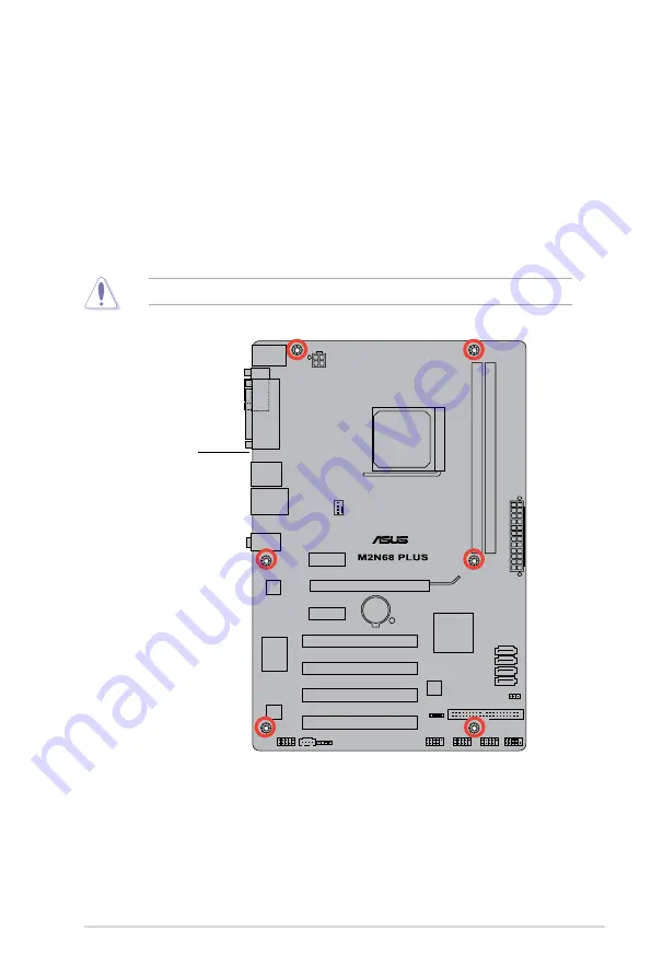
1.5.2
Screw holes
Place six (6) screws into the holes indicated by circles to secure the motherboard to the
chassis.
Do not overtighten the screws! Doing so can damage the motherboard.
Place this side towards
the rear of the chassis.
Chapter 1: Product introduction
1-5
Содержание M2N68 PLUS
Страница 1: ...Motherboard M2N68 PLUS ...


