


ASUS KFN5-D SLI
4-3
2. Copy the AFUDOS utility (afudos.exe) from the motherboard support
CD to the bootable floppy disk you created earlier.
3. Boot the system in DOS mode, then at the prompt type:
afudos /i[filename]
where [filename] is the latest or the original BIOS file on the bootable
floppy disk.
Updating the BIOS file
To update the BIOS file using the AFUDOS utility:
1. Visit the ASUS website (www.asus.com) and download the latest BIOS
file for the motherboard. Save the BIOS file to a bootable floppy disk.
A:\>afudos /iKFN5-D.ROM
Write the BIOS filename on a piece of paper. You need to type the exact
BIOS filename at the DOS prompt.
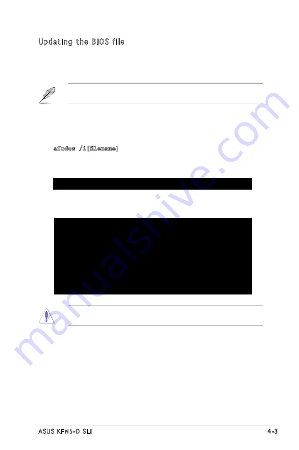
A:\>afudos /iKFN5-D.ROM
AMI Firmware Update Utility - Version 1.19(ASUS V2.07(03.11.24BB))
Copyright (C) 2002 American Megatrends, Inc. All rights reserved.
WARNING!! Do not turn off power during flash BIOS
Reading file ....... done
Reading flash ...... done
Advance Check ......
Erasing flash ...... done
Writing flash ...... 0x0008CC00 (9%)
4. The utility verifies the file and starts updating the BIOS.
Do not shut down or reset the system while updating the BIOS to
prevent system boot failure!
Содержание KFN5-D - Motherboard - SSI EEB 3.51
Страница 1: ...Motherboard KFN5 D SLI ...
Страница 13: ...1 Product introduction This chapter describes the motherboard features and the new technologies it supports ...
Страница 14: ...ASUS KFN5 D SLI Chapter summary 1 1 1 Welcome 1 1 1 2 Package contents 1 1 1 3 Special features 1 2 ...
Страница 108: ...4 42 Chapter 4 BIOS setup ...
Страница 109: ...5 RAID support This chapter provides information on RAID configurations for this motherboard ...
Страница 128: ...5 18 Chapter 5 RAID configuration ...
Страница 129: ...6 Driver installation This chapter provides information on RAID LAN and VGA driver installation for this motherboard ...
Страница 146: ...6 16 Chapter 6 Driver installation ...


