Asus KCMR-D12 Скачать руководство пользователя страница 54

2-36

Chapter 2: Hardware information

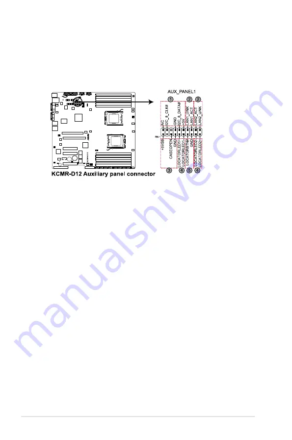
11.  Auxiliary panel connector (20-pin AUX_PANEL1)

This connector is for additional front panel features including front panel 
SMB, locator LED and switch, chassis intrusion, and LAN LEDs.

1.  Front panel SMB (6-1 pin FPSMB)


These leads connect the front panel SMBus cable.

2.  LAN activity LED (2-pin LAN1_LED, LAN2_LED

These leads are for Gigabit LAN activity LEDs on the front panel.

3.  Chassis intrusion (4-1 pin CHASSIS)


These leads are for the intrusion detection feature for chassis with 
intrusion sensor or microswitch. When you remove any chassis 
component, the sensor triggers and sends a high-level signal to these 
leads to record a chassis intrusion event. The default setting is short 
CASEOPEN and GND pin by jumper cap to disable the function.

4.  Locator LED (2-pin LOCATORLED1 and 2-pin LOCATORLED2)


These leads are for the locator LED1 and LED2 on the front panel. 
Connect the Locator LED cables to these 2-pin connector. The LEDs will 
light up when the Locator button is pressed. 

5.  Locator Button/Swich (2-pin LOCATORBTN)


These leads are for the locator button on the front panel. This button 
queries the state of the system locator.

Содержание KCMR-D12

Страница 1: ...Motherboard KCMR D12 ...

Страница 2: ...MERCHANTABILITY OR FITNESS FOR A PARTICULAR PURPOSE IN NO EVENT SHALL ASUS ITS DIRECTORS OFFICERS EMPLOYEES OR AGENTS BE LIABLE FOR ANY INDIRECT SPECIAL INCIDENTAL OR CONSEQUENTIAL DAMAGES INCLUDING DAMAGES FOR LOSS OF PROFITS LOSS OF BUSINESS LOSS OF USE OR DATA INTERRUPTION OF BUSINESS AND THE LIKE EVEN IF ASUS HAS BEEN ADVISED OF THE POSSIBILITY OF SUCH DAMAGES ARISING FROM ANY DEFECT OR ERROR ...

Страница 3: ...erboard overview 2 6 2 2 1 Placement direction 2 6 2 2 2 Screw holes 2 6 2 2 4 Motherboard layouts 2 7 2 2 5 Layout contents 2 8 2 3 Central Processing Unit CPU 2 10 2 3 1 Installing the CPU 2 10 2 3 2 Installing the CPU heatsink and fan 2 13 2 3 3 Installing the CPU heatsink 2 16 2 4 System memory 2 17 2 4 1 Overview 2 17 2 4 2 Memory Configurations 2 18 2 4 3 Installing a DIMM 2 19 2 4 4 Removin...

Страница 4: ...er 3 4 3 2 1 Using the OS shut down function 3 4 3 2 2 Using the dual function power switch 3 4 Chapter 4 BIOS setup 4 1 Managing and updating your BIOS 4 3 4 1 1 ASUS EZ Flash 2 utility 4 3 4 1 2 BUPDATER utility 4 4 4 1 2 ASUS CrashFree BIOS 3 utility 4 6 4 2 BIOS setup program 4 7 4 2 1 BIOS menu screen 4 8 4 2 2 Menu bar 4 8 4 2 3 Navigation keys 4 8 4 2 4 Menu items 4 9 4 2 5 Sub menu items 4...

Страница 5: ...vice Priority 4 33 4 7 2 Hard Disk Drives CDROM Drives 4 33 4 7 3 Boot Settings Configuration 4 34 4 7 4 Security 4 35 4 8 Tools menu 4 37 4 8 1 ASUS EZ Flash 2 4 37 4 9 Exit menu 4 38 Exit and Save Changes 4 38 Exit and Discard Changes 4 38 Discard Changes 4 38 Load Setup Defaults 4 38 Chapter 5 RAID configuration 5 1 Setting up RAID 5 3 5 1 2 Installing hard disk drives 5 4 5 1 3 Setting the RAI...

Страница 6: ...ation 6 15 6 3 LAN driver installation 6 19 6 4 ATI SM Bus controller driver installation 6 23 6 5 Display driver installation 6 24 6 6 Management applications and utilities installation 6 27 6 6 1 Running the support DVD 6 27 6 6 2 Drivers menu 6 27 6 6 3 Utilities menu 6 28 6 6 4 Make disk menu 6 28 6 6 5 Contact information 6 28 Appendix Reference information A 1 KCMR D12 block diagram A 3 ...

Страница 7: ...on the user is encouraged to try to correct the interference by one or more of the following measures Reorient or relocate the receiving antenna Increase the separation between the equipment and receiver Connect the equipment to an outlet on a circuit different from that to which the receiver is connected Consult the dealer or an experienced radio TV technician for help Canadian Department of Comm...

Страница 8: ... the power supply is broken do not try to fix it by yourself Contact a qualified service technician or your retailer Operation safety Before installing the motherboard and adding devices on it carefully read all the manuals that came with the package Before using the product make sure all cables are correctly connected and the power cables are not damaged If you detect any damage contact your deal...

Страница 9: ...s Detailed descriptions of the BIOS parameters are also provided Chapter 5 RAID configuration This chapter provides instructions for setting up creating and configuring RAID sets using the available utilities Chapter 6 Driver installation This chapter provides instructions for installing the necessary drivers for different system components Appendix Reference information This appendix includes add...

Страница 10: ...key Key1 Key2 Key3 If you must press two or more keys simultaneously the key names are linked with a plus sign Example Ctrl Alt D Command Means that you must type the command exactly as shown then supply the required item or value enclosed in brackets Example At the DOS prompt type the command line format A S DANGER WARNING Information to prevent injury to yourself when trying to complete a task C...

Страница 11: ...ansion Slots follow SSI Loacation Total PCI PCI X PCI E Slots 5 Slot Loacation 1 1 PCI E x8 Gen2 X4 X0 Link share with additional slot 1 Slot Loacation 3 1 PCI E x8 Gen2 X8 Link Slot Loacation 4 1 PCI E x8 Gen2 X8 X0 Link share with slot 6 Slot Loacation 6 1 PCI E x16 Gen2 X16 8 Link auto switch with slot4 Slot Loacation 7 1 PCI 32bit 33 MHz Additional Slot 1 1 PIKE Slot for Stroage expansion Stor...

Страница 12: ... Connectors 1 x USB connector Type A USB socket 2 x USB pin headers up to 4 devices Fan Header 8 4pin SMBus 2 Chassis intruder 1 Front LAN LED 2 Serial Port Header 1 GPTPM header 1 Rear I O Connectors External Serial Port 1 External USB Port 2 VGA Port 1 RJ 45 3 One for BMC 2 for LAN PS 2 KB Mouse 1 Management Solution Software ASWM Out of Band Remote Management Optional ASMB4 iKVM for KVM over IP...

Страница 13: ...1 Product introduction This chapter describes the motherboard features and the new technologies it supports ...

Страница 14: ...ASUS KCMR D12 Chapter summary 1 1 1 Welcome 1 3 1 2 Package contents 1 3 1 3 Serial number label 1 4 1 4 Special features 1 4 ...

Страница 15: ...ling the motherboard and hardware devices on it check the items in your package with the list below 1 2 Package contents Check your motherboard package for the following items If any of the above items is damaged or missing contact your retailer Standard Gift Box Pack Standard Bulk Pack Cable SATA data 6 Thermal sensor 1 Accessory I O Shield 1 1 Application CD Support CD 1 1 Documentation User Gui...

Страница 16: ...just 1 5V for DDR3 This voltage reduction limits the power consumption and heat generation of DDR3 which makes it an ideal memory solution The motherboard also supports 1 35V DDR3 LVDIMMs AMD 4 6 Core Architecture The motherboard supports AMD 4 6 core processors with discrete L2 cache structure for each core and shared L3 cache to meet demands for more powerful computing HyperTransport technology ...

Страница 17: ...TA products with a host of new features including Native Command Queuing NCQ Power Management PM Implementation Algorithm and Hot Swap Serial ATA allows thinner more flexible cables with lower pin count and reduced voltage requirements USB 2 0 technology The motherboard implements the Universal Serial Bus USB 2 0 specification dramatically increasing the connection speed from the 12 Mbps bandwidth...

Страница 18: ... operation PIKE Proprietary I O Kit Expansion PIKE is an on demand upgrade kit for users This ASUS unique feature enables users to choose their preferred I O solutions ASUS provides multiple SAS solutions for different segments and purposes and PIKE saves lots of validation efforts and hardware cost for end users Moreover the special patent design offers multiple I O solutions without occupying th...

Страница 19: ... Hardware information This chapter lists the hardware setup procedures that you have to perform when installing system components It includes description of the jumpers and connectors on the motherboard ...

Страница 20: ... KCMR D12 Chapter summary 2 2 1 Before you proceed 2 3 2 2 Motherboard overview 2 6 2 3 Central Processing Unit CPU 2 10 2 4 System memory 2 17 2 5 Expansion slots 2 20 2 6 Jumpers 2 25 2 7 Connectors 2 29 ...

Страница 21: ...ll any component place it on a grounded antistatic pad or in the bag that came with the component Before you install or remove any component ensure that the power supply is switched off or the power cord is detached from the power supply Failure to do so may cause severe damage to the motherboard peripherals and or components Onboard LED 1 Standby Power LED The motherboard comes with a standby pow...

Страница 22: ...U2 The CPU warning LEDs light up to indicate that an impending failure of the corresponding CPU 3 DIMM warning LED ERR_DIMMA1 2 3 ERR_DIMMB1 2 3 ERR_DIMMC1 2 3 ERR_DIMMD1 2 3 The DIMM warning LEDs light up to indicate that an impending failure of the corresponding DIMMs ...

Страница 23: ... heartbeat LED blinks per second to indicate that the ASMB4 is working normally The heartbeat LED functions only when you install the ASUS ASMB4 Everytime after the AC power is replugged you have to wait for about 30 seconds for the system power up ...

Страница 24: ...e that you place it into the chassis in the correct orientation The edge with external ports goes to the rear part of the chassis as indicated in the image below 2 2 2 Screw holes Place nine 9 screws into the holes indicated by circles to secure the motherboard to the chassis DO NOT overtighten the screws Doing so can damage the motherboard Ensure to unplug the chassis power cord before installing...

Страница 25: ...ASUS KCMR D12 2 7 2 2 4 Motherboard layouts ...

Страница 26: ...SW1 2 26 3 DDR3 voltage control setting 4 pin LVDDR3_SEL1 LVDDR3_SEL2 2 26 4 LAN controller setting 3 pin LAN_SW1 LAN_SW2 2 27 5 CPU Fan and Chassis Fan control setting 3 pin CPUFAN_SEL1 CHAFAN_SEL1 2 27 6 Force BIOS recovery setting 3 pin RECOVERY1 2 28 Rear panel connectors Page 1 PS 2 mouse port green 2 29 2 RJ 45 port for iKVM 2 29 3 PS 2 keyboard port purple 2 29 4 USB 2 0 ports 1 and 2 2 29 ...

Страница 27: ...ype USB8 2 31 4 Front fan connectors 4 pin CPU_FAN1 2 REAR_FAN1 2 FRNT_FAN1 4 2 32 5 Serial General Purpose Input Output connector 6 1 pin SGPIO1 2 3 4 2 32 6 BMC header BMC_FW1 2 33 7 Thermal sensor cable connectors 3 pin TR1 TR2 2 33 8 SSI power connectors 24 pin ATXPWR1 8 pin ATX12V1 8 pin ATX12V2 2 34 9 Location LED cable connector 3 pin LOCLED1 2 34 10 System panel connector 20 pin PANEL1 2 3...

Страница 28: ...the damage is shipment transit related Keep the cap after installing the motherboard ASUS will process Return Merchandise Authorization RMA requests only if the motherboard comes with the cap on the Socket 1207 The product warranty does not cover damage to the socket contacts resulting from incorrect CPU installation removal or misplacement loss incorrect removal of the PnP cap 2 3 1 Installing th...

Страница 29: ...ap from the CPU socket PnP cap The CPU fits in only one correct orientation DO NOT force the CPU into the socket to prevent bending the connectors on the socket and damaging the CPU 6 Position the CPU over the socket ensuring that the gold triangle is on the bottom left corner of the socket and then fit the socket alignment key into the CPU notch Gold triangle mark Alignment key CPU notch ...

Страница 30: ...tsinks come with pre applied Thermal Interface Material If so skip this step The Thermal Interface Material is toxic DO NOT eat the Thermal Interface Material If it gets into your eyes or touches your skin ensure that you wash it off immediately and seek professional medical help To prevent contaminating the Thermal Interface Material DO NOT spread the Thermal Interface Material with your finger d...

Страница 31: ...s section do not match the CPU documentation follow the latter Retention module base CPU heatsink CPU fan Retention bracket lock Retention bracket The retention module base is already installed on the motherboard upon purchase You do not have to remove the retention module base when installing the CPU or installing other motherboard components Ensure that you use only AMD certified heatsink and fa...

Страница 32: ...n bracket lock to the retention module base A clicking sound denotes that the retention bracket is in place 4 Push down the retention bracket lock on the retention mechanism to secure the heatsink and fan to the module base Ensure that the fan and heatsink assembly perfectly fits the retention mechanism module base otherwise you cannot snap the retention bracket in place ...

Страница 33: ...fan cable to the corresponding connector on the motherboard Do not forget to connect the CPU fan connector Hardware monitoring errors can occur if you fail to plug this connector This connector is backward compatible with old 3 pin CPU fan ...

Страница 34: ...ssembly only Ensure that you have applied the thermal grease to the top of the CPU before installing the heatsink Follow these steps to install the CPU heatsink 1 Orient and place the heatsink on top of the installed CPU ensuring that the screw holes are matched with the heatsink standoffs 2 Use a Phillips screwdriver to tighten the two heatsink screws Ensure that the heatsink is not skewed or til...

Страница 35: ... Dual Inline Memory Modules DIMM sockets A DDR3 module has the same physical dimensions as a DDR2 DIMM but is notched differently to prevent installation on a DDR2 DIMM socket DDR3 modules are developed for better performance with less power consumption The figure illustrates the location of the DDR3 DIMM sockets ...

Страница 36: ... 35V Timing Mode UDIMM SR DR 800 800 1T SR DR SR DR 800 800 1T SR DR 1066 1066 1T SR DR SR DR 1066 1066 1T SR DR 1333 1333 1T SR SR 1333 1333 2T DR DR 1333 2T SR DR 1333 2T DR SR 1333 2T RDIMM SR DR 667 667 SR DR SR DR 667 667 QR SR DR 667 667 SR DR SR DR SR DR 667 667 SR DR QR SR DR 667 667 SR DR 800 800 SR DR SR DR 800 800 QR SR DR 800 SR DR SR DR SR DR 800 800 QR 800 800 SR DR 1066 1066 SR DR S...

Страница 37: ...s snap back in place and the DIMM is properly seated 2 4 4 Removing a DIMM To remove a DIMM 1 Simultaneously press the retaining clips outward to unlock the DIMM 2 Remove the DIMM from the socket A DDR3 DIMM is keyed with a notch so that it fits in only one direction DO NOT force a DIMM into a socket to avoid damaging the DIMM The DDR3 DIMM sockets do not support DDR and DDR2 DIMMs DO NOT install ...

Страница 38: ...y seated on the slot 5 Secure the card to the chassis with the screw you removed earlier 6 Replace the system cover 2 5 2 Configuring an expansion card After installing the expansion card configure the it by adjusting the software settings 1 Turn on the system and change the necessary BIOS settings if any See Chapter 4 for information on BIOS setup 2 Assign an IRQ to the card Refer to the tables o...

Страница 39: ...rrupt 4 12 Communications Port COM1 5 13 6 14 Floppy Disk Controller 7 15 8 3 System CMOS Real Time Clock 9 4 ACPI Mode when used 10 5 IRQ Holder for PCI Steering 11 6 IRQ Holder for PCI Steering 12 7 PS 2 Compatible Mouse Port 13 8 Numeric Data Processor 14 9 Primary IDE Channel 15 10 Secondary IDE Channel 2 5 3 Interrupt assignments Standard Interrupt assignments ...

Страница 40: ...r class high performance add on cards 2 5 6 PCI Express x16 slot x16 x8 link The onboard PCI Express x16 slot provides x16 link to CPU It automatically switches to x8 link when the slot 4 is occupied This slot supports VGA cards and various server class high performance add on cards 2 5 7 PIKE slot The PIKE slot allows you to choose and change your preferred SAS solution easily Install an optional...

Страница 41: ...anagement board on your motherboard 1 Locate the BMC_FW1 header on the motherboard 2 Orient and press the ASMB4 management board in place 2 5 9 Installing i Button Follow the steps below to install an optional i Button on your motherboard 1 Locate the i Button slot on the motherboard 2 Snap the i Button in place ...

Страница 42: ...w to install an optional ASUS RAID card on your motherboard 1 Locate the PIKE RAID card slot on the motherboard 2 Align the golden fingers of the RAID card with the PIKE RAID card slot 3 Insert the RAID card into the PIKE RAID card slot Make sure it is completely seated on the PIKE RAID card slot ...

Страница 43: ... and unplug the power cord 2 Move the jumper cap from pins 1 2 default to pins 2 3 Keep the cap on pins 2 3 for about 5 10 seconds then move the cap back to pins 1 2 3 Plug the power cord and turn ON the computer 4 Hold down the Del key during the boot process and enter BIOS setup to re enter data Except when clearing the RTC RAM never remove the cap on CLRTC jumper default position Removing the c...

Страница 44: ...enable or disable the onboard VGA controller Set to pins 1 2 to activate the VGA feature 3 DDR3 voltage control setting 4 pin LVDDR3_SEL1 LVDDR3_SEL2 These jumpers allow you to adjust the DIMM voltage Set to pins 1 2 to select 1 5V BIOS control pins 2 3 to select 1 2V Force or 3 4 to select 1 35V Force ...

Страница 45: ...L1 These jumpers allow you to switch for fan pin selection The CPUFAN_SEL1 jumper is for the CPU fan control and the CHAFAN_SEL1 jumper is for the front fans and rear fans control Set to pins 1 2 when using 4 pin fans or pins 2 3 when using 3 pin fans If you use a 4 pin fan but set the jumper to pin 2 3 the fan you installed may not work If you use a 3 pin fan but set the jumper for a 4 pin fan th...

Страница 46: ...ings when it becomes corrupted To update the BIOS 1 Prepare a USB flash disk that contains the original or latest BIOS for the motherboard XXXXXX ROM and the AFUDOS EXE utility 2 Set the jumper to pins 2 3 3 Insert the USB flash and turn on the system to update the BIOS 4 Shut down the system 5 Set the jumper back to pins 1 2 6 Turn on the system ...

Страница 47: ...l devices 6 Video Graphics Adapter port This port is for a VGA monitor or other VGA compatible devices 7 LAN 1 RJ 45 port This port allows Gigabit connection to a Local Area Network LAN through a network hub Refer to the table below for the LAN port LED indications 8 LAN 2 RJ 45 port This port allows Gigabit connection to a Local Area Network LAN through a network hub Refer to the table below for ...

Страница 48: ...hese connectors are for the Serial ATA signal cables for Serial ATA hard disk drives that allows up to 3Gb s of data transfer rate If you installed Serial ATA hard disk drives you can create a RAID 0 RAID 1 RAID 10 or RAID 5 configuration The actual data transfer rate depends on the speed of Serial ATA hard disks installed The SATA connectors do not support SATA cables with latch ...

Страница 49: ...ctors comply with USB 2 0 specification that supports up to 480 Mbps connection speed 2 SAS connectors 7 pin SAS1 SAS2 SAS3 SAS4 Red 7 pin SAS5 SAS6 SAS7 SAS8 Blue This motherboard comes with eight 8 Serial Attached SCSI SAS connectors the next generation storage technology that supports both Serial Attached SCSI SAS and Serial ATA SATA Each connector supports one device These SAS connectors funct...

Страница 50: ...the black wire of each cable matches the ground pin of the connector DO NOT forget to connect the fan cables to the fan connectors Insufficient air flow inside the system may damage the motherboard components These are not jumpers DO NOT place jumper caps on the fan connectors All fans feature the ASUS Smart Fan technology 5 Serial General Purpose Input Output connector 6 1 pin SGPIO1 2 3 4 This c...

Страница 51: ...pports an ASUS Server Management Board 4 Series ASMB4 7 Thermal sensor cable connectors 3 pin TR1 TR2 These connectors are for temperature monitoring Connect the thermal sensor cables to these connectors and place the other ends to the devices which you want to monitor temperature ...

Страница 52: ...letely fit Do not forget to connect the 24 8 8 pin power plugs otherwise the system will not boot up Use of a PSU with a higher power output is recommended when configuring a system with more power consuming devices The system may become unstable or may not boot up if the power is inadequate You must install a PSU with a higher power rating if you intend to install additional devices 9 Location LE...

Страница 53: ...4 pin connector is for the chassis mounted system warning speaker The speaker allows you to hear system beeps and warnings 4 Hard disk drive activity LED 2 pin HDDLED This 2 pin connector is for the HDD Activity LED Connect the HDD Activity LED cable to this connector The IDE LED lights up or flashes when data is read from or written to the HDD 5 Proprietary power button soft off button 2 pin PWRS...

Страница 54: ...detection feature for chassis with intrusion sensor or microswitch When you remove any chassis component the sensor triggers and sends a high level signal to these leads to record a chassis intrusion event The default setting is short CASEOPEN and GND pin by jumper cap to disable the function 4 Locator LED 2 pin LOCATORLED1 and 2 pin LOCATORLED2 These leads are for the locator LED1 and LED2 on the...

Страница 55: ...3 Powering up This chapter describes the power up sequence and ways of shutting down the system ...

Страница 56: ...ASUS KCMR D12 Chapter summary 3 3 1 Starting up for the first time 3 3 3 2 Turning off the computer 3 4 ...

Страница 57: ...ts up For systems with Proprietary power supplies the system LED lights up when you press the Proprietary power button If your monitor complies with green standards or if it has a power standby feature the monitor LED may light up or switch between orange and green after the system LED turns on The system then runs the power on self test or POST While the tests are running the BIOS beeps or additi...

Страница 58: ... the Planned check box is checked 5 Select shutdown from the list box 6 If necessary key in comments 7 Click OK 3 2 2 Using the dual function power switch While the system is ON pressing the power switch for less than four seconds puts the system to sleep mode or to soft off mode depending on the BIOS setting Pressing the power switch for more than four seconds lets the system enter the soft off m...

Страница 59: ...4 BIOS setup This chapter tells how to change the system settings through the BIOS Setup menus Detailed descriptions of the BIOS parameters are also provided ...

Страница 60: ...SUS KCMR D12 4 1 Managing and updating your BIOS 4 3 4 2 BIOS setup program 4 7 4 3 Main menu 4 10 4 4 Advanced menu 4 15 4 5 Server menu 4 27 4 6 Power menu 4 29 4 7 Boot menu 4 33 4 8 Tools menu 4 37 4 9 Exit menu 4 38 ...

Страница 61: ...S in the future Copy the original motherboard BIOS using the BUPDATER utility 4 1 1 ASUS EZ Flash 2 utility The ASUS EZ Flash 2 feature allows you to update the BIOS without having to use a DOS based utility Before you start using this utility download the latest BIOS from the ASUS website at www asus com To update the BIOS using EZ Flash 2 1 Insert the USB flash disk that contains the latest BIOS...

Страница 62: ...IOS screens are for reference only The actual BIOS screen displays may not be the same as shown The BUPDATER utility allows you to update the BIOS file in DOS environment using a bootable USB flash disk drive with the updated BIOS file Updating the BIOS file To update the BIOS file using the BUPDATER utility 1 Visit the ASUS website at www asus com and download the latest BIOS file for the motherb...

Страница 63: ...OS Update for DOS V1 06 09 08 04 Current ROM Update ROM Note Writing BIOS FLASH TYPE MXIC 25L1605A PATH BOARD KCMR D12 VER 0301 DATE 10 08 2010 BOARD VER DATE 5 The utility returns to the DOS prompt after the BIOS update process is completed Reboot the system from the hard disk drive The BIOS update is finished Please restart your system C WARNING Do not turn off power during flash BIOS ...

Страница 64: ...vering the BIOS from a USB flash drive To recover the BIOS from a USB flash drive 1 Remove any floppy disk from the floppy disk drive and turn the system on 2 Insert the USB flash drive with the original or updated BIOS file to one USB port on the system 3 The utility will automatically recover the BIOS It resets the system when the BIOS recovery finished DO NOT shut down or reset the system while...

Страница 65: ...ress Del during the Power On Self Test POST to enter the Setup utility otherwise POST continues with its test routines If you wish to enter Setup after POST restart the system by pressing Ctrl Alt Delete or by pressing the reset button on the system chassis You can also restart by turning the system off and then back on Do this last option only if the first two failed The Setup program is designed...

Страница 66: ...system boot configuration Tools For configuring options for special functions Exit For selecting the exit options and loading default settings To select an item on the menu bar press the right or left arrow key on the keyboard until the desired item is highlighted 4 2 3 Navigation keys At the bottom right corner of a menu screen are the navigation keys for that particular menu Use the navigation k...

Страница 67: ...is highlighted when selected To change the value of a field select it then press Enter to display a list of options Refer to 4 2 7 Pop up window 4 2 7 Pop up window Select a menu item then press Enter to display a pop up window with the configuration options for that item 4 2 8 Scroll bar A scroll bar appears on the right side of a menu screen when there are items that do not fit on the screen Pre...

Страница 68: ...ration System Information Select Screen Select Item Change Field Tab Select Field F1 General Help F10 Save and Exit ESC Exit 4 3 3 SATA1 6 While entering Setup the BIOS automatically detects the presence of IDE SATA devices There is a separate submenu for each IDE SATA device Select a device item then press Enter to display the SATA device information v02 61 C Copyright 1985 2010 American Megatren...

Страница 69: ...s data multi sectors transfers When set to Auto the data transfer from and to the device occurs multiple sectors at a time if the device supports multi sector transfer feature When set to Disabled the data transfer from and to the device occurs one sector at a time Configuration options Disabled Auto PIO Mode Auto Allows you to select the data transfer mode Configuration options Auto 0 1 2 3 4 DMA...

Страница 70: ...ort4 IDE SATA Port5 Port6 IDE Select Screen Select Item Change Option F1 General Help F10 Save and Exit ESC Exit Options Disabled Enabled OnChip SATA Channel Enabled Configuration options Disabled Enabled SATA Port1 Port4 IDE Sets the configuration for the Serial ATA connectors Configuration options IDE RAID AHCI SATA Port5 Port6 Setting this item to IDE allows the system to recognize the optical ...

Страница 71: ...Hz System Memory Usable Size 1024MB System Memory Information Select Screen Select Item Enter Go to Sub Screen F1 General Help F10 Save and Exit ESC Exit BIOS SETUP UTILITY Main System Memory Information CPU1 Memory Information CPU2 Memory Information BIOS Information Displays the auto detected BIOS information Processor Displays the auto detected CPU specification System Memory Displays the auto ...

Страница 72: ... setup BIOS SETUP UTILITY Main CPU1 Memory Configuration Node0 Speed N A DIMM_A1 N A DIMM_A2 N A DIMM_A3 N A DIMM_B1 N A DIMM_B2 N A DIMM_B3 N A CPU1 2 Memory Configuration Displays the auto detected memory specification ...

Страница 73: ...the CPU related information that the BIOS automatically detects Some items may not appear if your CPU does not support the related functions v02 61 C Copyright 1985 2010 American Megatrends Inc BIOS SETUP UTILITY Advanced CPU Configuration Module Version 5 1104 1 Socket Count 1 Node Count 1 Core Count 6 AMD Opteron tm Processor 4122 Revision D0 Cache L1 512KB Cache L2 2048KB Cache L3 6MB Speed 220...

Страница 74: ...dation Enabled Configuration options Disabled Enabled Secure Virtual Machine Mode Enabled Allows you to enable or diable the Secure Virtual Machine Mode SVM Configuration options Disabled Enabled PowerNow Enabled Allows you to enable or diable the generation of ACPI_PPC ACPI_PSS and ACPI_PCT objects Configuration options Disabled Enabled PowerCap P state 0 Allows you to decide the highest performa...

Страница 75: ...ng the settings Configuration optitons Auto Maximum Core Level No Leveling 2 Cores 4 Cores C1E Support Enabled Allows you to enable or disable Enhanced Halt State support Configuration options Disabled Enabled CPU2 Enabled Allows you to enable or disable the CPU2 function Configuration options Disabled Enabled ...

Страница 76: ...66 Mhz CSI Links Speed Full Speed CSI Frequency Auto Memory Frequency Auto Memory Mode Independent Demand Scrubbing Disabled Patrol Scrubbing Disabled Throttling Closed Loop Disabled Throttling Open Loop Disabled Select Screen Select Item Change Option F1 General Help F10 Save and Exit ESC Exit To transition the CSI links to full speed or leave them in slow mode v02 61 C Copyright 1985 2010 Americ...

Страница 77: ...Channel Interleaving Auto CS Sparing Enabled Disabled Bank Swizzle Mode Enabled Channel B Enabled Channel C Enabled Channel D Enabled Select Screen Select Item Change Option F1 General Help F10 Save and Exit ESC Exit Rank Interleaving Auto Allows you to set the rank memory interleaving setting Configuation options Disabled Auto Node Interleaving Disabled Allows you to set the node memory interleav...

Страница 78: ...Disabled Allows the L1 Data Cache ram to be corrected while idle Configuration options Disabled 40ns 80ns 160ns 320ns 640ns 1 28us 2 56us 5 12us 10 2us 20 5us 41 0us 81 9us 163 8us 327 7us 655 4us 1 31ms 2 62ms 5 24ms 10 49ms 20 97ms 42 00ms 84 00ms ECC Configuration v02 61 C Copyright 1985 2008 American Megatrends Inc BIOS SETUP UTILITY Advanced CPU Bridge Chipset Configuration CPU REVISION B0 Cu...

Страница 79: ...y when you set DRAM Timing Config to Manual Configuration options 333 MHz 400 MHz 533 MHz 667 MHz DRAM Timing Configuration v02 61 C Copyright 1985 2008 American Megatrends Inc BIOS SETUP UTILITY Advanced CPU Bridge Chipset Configuration CPU REVISION B0 Current CSI Frequency 6 400GT Current Memory Frequency 1066 Mhz CSI Links Speed Full Speed CSI Frequency Auto Memory Frequency Auto Memory Mode In...

Страница 80: ...ican Megatrends Inc Onchip HD Azalia Configuration Advanced HD Audio Azalia Device Auto HD Onboard PIN Config Enabled Azalia Front Panel Auto SDIN0 Pin Config Azalia SDIN1 Pin Config Azalia SDIN2 Pin Config Azalia SDIN3 Pin Config Azalia Azalia Snoop Disabled Azalia Clock Gating Disabled Select Screen Select Item Change Option F1 General Help F10 Save and Exit ESC Exit Auto When MIO is installed t...

Страница 81: ...rts Auto Clk Ctrl Disabled SATA PORT0 MODE Auto SATA PORT1 MODE Auto SATA PORT2 MODE Auto SATA PORT3 MODE Auto SATA PORT4 MODE Auto SATA PORT5 MODE Auto Select Screen Select Item Change Option F1 General Help F10 Save and Exit ESC Exit Options Disabled Enabled A15 ECOs Disabled Configuration options Disabled Enabled Port 0 5 ESP ISP Allows you to decide the ESP help Configuration options ISP ESP D...

Страница 82: ...options Disabled L0s L1 L0s L1 L0s Downstream L0s Downstream L1 Compliance Mode Disabled Configuration options Disabled Enabled SATA AHCI Ports Auto Clk Ctrl Disabled When set to Enabled the clocks for unused SATA ports in AHCI mode will be shut down and the system saves some power but the hotplug function for those ports will be unavailable Configuration options Disabled Enabled SATA PORT 0 5 MOD...

Страница 83: ...d Enabled TX Drive Strength Auto Configuration options Auto 26mA 20mA 22mA 24mA TXCLK Clock Gating in L1 Enabled Configuration options Disabled Enabled LCLK Clock Gating in L1 Enabled Configuration options Disabled Enabled SB Core Setting TX Drive Strength Auto Configuration options Auto 26mA 20mA 22mA 24mA TXCLK Clock Gating in L1 Enabled Configuration options Disabled Enabled LCLK Clock Gating i...

Страница 84: ...OMMU Disabled Configuration options Disabled Enabled VGA ROM Boot Priority PCIE VGA Card Allows you to set the VGA ROM boot priority Configuration options PCIE VGA Card Onboard VGA Debug Option Memory Decode on Sec GFX Disabled Configuration options Disabled Force IOC Peer to Peer Mode Auto Configuration options Auto Default Mode 1 Mode 2 Northbridge interrupt pin Disabled Configuration options Di...

Страница 85: ...n Megatrends Inc BIOS SETUP UTILITY Main Advanced Server Power Boot Tools Exit Remote Access Configuration Select Screen Select Item Change Option F1 General Help F10 Save and Exit ESC Exit v02 61 C Copyright 1985 2010 American Megatrends Inc BIOS SETUP UTILITY Server Configure Remote Access type and parameters Remote Access Enabled Serial port number COM2 Base Address IRQ 2F8h 3 Serial Port Mode ...

Страница 86: ...n options 115200 8 n 1 57600 8 n 1 38400 8 n 1 19200 8 n 1 09600 8 n 1 Flow Control Hardware Allows you to select the flow control for console redirection Configuration options None Hardware Software Redirection After BIOS POST Disabled Sets the redirection mode after the BIOS Power On Self Test POST Some operating system may not work when set to Always Configuration options Disabled Boot Loader A...

Страница 87: ...used for system suspend Configuration options S1 POS only S3 only Auto 4 6 2 Repost Video on S3 Resume No Allows you to determine whether to incoke VGA BIOS post on S3 STR resume Configuration options No Yes 4 6 3 ACPI 2 0 Support ACPI v2 0 Specifies the Advanced Configuration and Power Interface ACPI version supported Configuration options ACPI v1 0 ACPI v2 0 ACPI v3 0 4 6 4 ACPI APIC Support Ena...

Страница 88: ...Last State the system goes into either off or on state whatever the system state was before the AC power loss Configuration options Power Off Power On Last State Resume On PCIE Wake Disabled Allows you to enable or disable the PCIE devices to generate a wake event Disabled Disables the PCIE devices to generate a wake event Enabled Enables the PCIE devices to generate a wake event Resume On Ring Di...

Страница 89: ...r Fan2 Speed N A Fan Speed Control Whisper Mode VCORE1 1 052 V VCORE2 1 052 V P1DDR3 Voltage 1 180 V P2DDR3 Voltage 1 180 V P1_ 1 2V Voltage 1 204 V Select Screen Select Item Change Option F1 General Help F10 Save and Exit ESC Exit CPU1 Temperature v02 61 C Copyright 1985 2010 American Megatrends Inc Select Screen Select Item Change Option F1 General Help F10 Save and Exit ESC Exit P2_ 1 2V Voltag...

Страница 90: ...gure the ASUS Smart Fan feature that smartly adjusts the fan speeds for more efficient system operation Configuration options Full Speed Mode Whisper Mode Generic Mode High Density Mode VCORE1 2 Voltage P1 2DDR3 Voltage P1_ 1 2V Voltage P2_ 1 2V Voltage P1_VDDNB Voltage 1 8V Voltage 1 2V Voltage 1 1V Voltage 12V Voltage 5V Voltage 3 3V Voltage 5VSB Voltage 3 3VSB Voltage VBAT Voltage The onboard h...

Страница 91: ...p F10 Save and Exit ESC Exit Specifies the Boot Device Priority sequence A virtual floppy disk drive Floppy Drive B may appear when you set the CD ROM drive as the first boot device v02 61 C Copyright 1985 2010 American Megatrends Inc BIOS SETUP UTILITY Boot Boot Device Priority 1st Boot Device Removable Dev 2nd Boot Device ATAPI CD ROM 3rd Boot Device Hard Drive 4th Boot Device Network B02 D00 Yu...

Страница 92: ...On Wait For F1 If Error Enabled When set to Enabled the system waits for the F1 key to be pressed when error occurs Configuration options Disabled Enabled Hit DEL Message Display Enabled When set to Enabled the system displays the message Press DEL to run Setup during POST Configuration options Disabled Enabled Interrupt 19 Capture Enabled Allows the option ROMs to trap interrupt 19 Configuration ...

Страница 93: ...d Installed appears after you successfully set your password To change the supervisor password follow the same steps as in setting a user password To clear the supervisor password select the Change Supervisor Password then press Enter The message Password Uninstalled appears If you forget your BIOS password you can clear it by erasing the CMOS Real Time Clock RTC RAM See section 2 6 Jumper for inf...

Страница 94: ...word this item shows Installed To set a User Password 1 Select the Change User Password item and press Enter 2 On the password box that appears type a password composed of at least six letters and or numbers then press Enter 3 Confirm the password when prompted The message Password Installed appears after you set your password successfully To change the user password follow the same steps as in se...

Страница 95: ... 2 Select Screen Select Item Enter Go to Sub Screen F1 General Help F10 Save and Exit ESC Exit Press ENTER to run the utility to select and update BIOS This uitlity supports 1 FAT 12 16 32 r w 2 NTFS read only 3 CD DISC read only 4 8 1 ASUS EZ Flash 2 Allows you to run ASUS EZ Flash 2 When you press Enter a confirmation message appears Use the left right arrow key to select between OK or Cancel th...

Страница 96: ... PC is turned off When you select this option a confirmation window appears Select YES to save changes and exit If you attempt to exit the Setup program without saving your changes the program prompts you with a message asking if you want to save your changes before exiting Press Enter to save the changes while exiting Exit and Discard Changes Select this option only if you do not want to save the...

Страница 97: ...5 RAID configuration This chapter provides instructions for setting up creating and configuring RAID sets using the available utilities ...

Страница 98: ...5 1 Setting up RAID 5 3 5 2 FastBuild Utility 5 5 ASUS KCMR D12 Chapter summary 5 ...

Страница 99: ... four new hard disk drives or use an existing drive and three new drives for this setup RAID 5 stripes both data and parity information across three or more hard disk drives Among the advantages of RAID 5 configuration include better HDD performance fault tolerance and higher storage capacity The RAID 5 configuration is best suited for transaction processing relational database applications enterp...

Страница 100: ...the back of each drive and to the SATA connector on the motherboard 3 Connect a SATA power cable to the power connector on each drive 5 1 3 Setting the RAID item in BIOS You must set the RAID item in the BIOS Setup before you can create a RAID set from SATA hard disk drives attached to the SATA connectors supported by AMD SP5100 chipset To do this 1 Enter the BIOS Setup during POST 2 Go to the Mai...

Страница 101: ...1 Install all the Serial ATA hard disk drives at Red SATA Connector 2 Turn on the system 3 During POST press Ctrl F to enter the utility main menu The RAID BIOS setup screens shown in this section are for reference only and may not exactly match the items on your screen Press 1 4 to Select Option ESC Exit FastBuild tm Utility c 2004 2010 Promise Technology Inc View Drive Assignment 1 LD View LD De...

Страница 102: ...ld tm Utility c 2004 2010 Promise Technology Inc There is no any LD LD View Menu Keys Available Up Down PaUp PaDn Switch Page Ctrl C Define LD Enter View LD Ctrl V View JBOD Disk ESC Exit Press 1 4 to Select Option ESC Exit FastBuild tm Utility c 2004 2010 Promise Technology Inc View Drive Assignment 1 LD View LD Define Menu 2 Delete LD Menu 3 Controller Configuration 4 Main Menu Keys Available ...

Страница 103: ... 04 01 HDTXXXXXXXXXXXX SATA 3G 250 05 N RAID Mode Drv RAID 1 0 Initialization Fast Write Policy WriteThru 3 Use Spacebar to set Read Policy to Read Cache and Write Policy to WriteBack FastBuild tm Utility c 2004 2010 Promise Technology Inc LD Define Menu Keys Available Up Down PaUp PaDn Switch Page Space Change Option Ctrl Y Save ESC Exit Drives Assignments LD No LD Name LD 1 Logical Drive 1 Strip...

Страница 104: ... 05 N 04 01 HDTXXXXXXXXXXXX SATA 3G 250 05 N Please Press Ctr Y key to input the LD name or press any key to exit If you do not input any LD name the default LD name will be used 4 After you have selected the desired RAID mode use the down arrow key to select desired disks for the RAID set FastBuild tm Utility c 2004 2010 Promise Technology Inc LD Define Menu Keys Available Up Down PaUp PaDn Switc...

Страница 105: ...N Enter the LD name here XXXX 7 All the data on the selected disk drives will be deleted Press Ctrl Y to continue FastBuild tm Utility c 2004 2010 Promise Technology Inc LD Define Menu Keys Available Up Down PaUp PaDn Switch Page Space Change Option Ctrl Y Save ESC Exit Drives Assignments LD No LD Name LD 1 Logical Drive 1 Stripe Block 128 KB Gigabyte Boundary ON Read Policy Read Cache RAID Mode D...

Страница 106: ...apacity in GB here 200 9 Use the number keys to enter your desired array capacity 8 Press Ctrl Y to modify the disk array size or press any other key to use all the available capacity of the disk drive FastBuild tm Utility c 2004 2010 Promise Technology Inc LD Define Menu Keys Available Drives Assignments LD No LD Name LD 1 Logical Drive 1 Stripe Block 128 KB Gigabyte Boundary ON Read Policy Read ...

Страница 107: ...AID Mode Drv Capacity GB Status LD 1 RAID 1 2 199 99 Functional 11 Press any key to return to the main control panel FastBuild tm Utility c 2004 2010 Promise Technology Inc View LD Definition Menu Any Key To Continue Drives Assignments LD No LD Name LD 1 RAID1 Stripe Block NA Read Policy Read Cache RAID Mode Drv Capacity GB RAID 1 2 199 99 Write Policy WriteBack Port ID Drive Model Capabilities Ca...

Страница 108: ...Drive Assignment 1 LD View LD Define Menu 2 Delete LD Menu 3 Controller Configuration 4 Main Menu Keys Available FastBuild tm Utility c 2004 2010 Promise Technology Inc Delete LD Menu Keys Available Up Down PaUp PaDn Switch Page Del Alt D Delete LD Ctrl V View JBOD Disk ESC Exit LD No RAID Mode Drv Capacity GB Status LD 1 RAID 1 2 199 99 Functional 2 Select the RAID set you would like to delete an...

Страница 109: ...ities Capacity GB 01 01 HDTXXXXXXXXXXXX SATA 3G 250 05 02 01 HDTXXXXXXXXXXXX SATA 3G 250 05 Keys Available Press Ctrl Y to delete the data in the disk or press any other key to abort 3 Press Ctrl Y to confirm and delete the selected RAID set FastBuild tm Utility c 2004 2010 Promise Technology Inc There is no any LD Delete LD Menu Keys Available Up Down PaUp PaDn Switch Page Del Alt D Delete LD Ctr...

Страница 110: ...ontroller Configuration 4 Main Menu Keys Available FastBuild tm Utility c 2004 2010 Promise Technology Inc View Drive Assignments Keys Available Ctrl H Full Erase ESC Exit Up Down PaUp PaDn Switch Page 2 The drive assignment is displayed as shown Port ID Drive Model Capabilities Capacity GB Assignment 01 01 HDTXXXXXXXXXXXX SATA 3G 250 05 Extent 1 249 99 Free 02 01 HDTXXXXXXXXXXXX SATA 3G 250 05 Ex...

Страница 111: ...004 2010 Promise Technology Inc View Drive Assignment 1 LD View LD Define Menu 2 Delete LD Menu 3 Controller Configuration 4 Main Menu Keys Available FastBuild tm Utility c 2004 2010 Promise Technology Inc Adapter Configuration Options ESC Exit System Resources Configuration Controller IRQ 10 AHCI HBA MMIO Base Address FAFFE400 No Parameters Defined for Current Disk s Keys Available 2 The system r...

Страница 112: ...5 16 Chapter 5 RAID configuration ...

Страница 113: ...6 Driver installation This chapter provides instructions for installing the necessary drivers for different system components ...

Страница 114: ...iver installation 6 3 6 2 AMD Processor Driver installation 6 15 6 3 LAN driver installation 6 19 6 4 ATI SM Bus controller driver installation 6 23 6 5 Display driver installation 6 24 6 6 Management application and utilities installation 6 27 ...

Страница 115: ...e a SATA optical drive and PROMISE RAID you cannot boot into FreeDOS using this support CD Either reset SATA Port1 4 in BIOS to IDE and boot again or create the RAID driver in another computer A floppy disk with the RAID driver is required when installing Windows or Red Hat Enterprise operating system on a hard disk drive that is included in a RAID set You can create a RAID driver disk in DOS usin...

Страница 116: ...river Windows Server 2003 32 64 bit Windows Server 2008 32 bit Windows Server 2008 64 bit Windows Server 2008 R2 64 bit RHEL AS4 UP8 32 bit RHEL AS4 UP8 64 bit RHEL 5 UP4 32 bit RHEL 5 UP4 64 bit SLES 10 SP3 32 bit SLES 10 SP3 64 bit SLES 11 32 bit SLES 11 64 bit CentOS 5 4 32 bit CentOS 5 4 64 bit Back Exit 5 Use the arrow keys to select the type of RAID driver disk you want to create and press E...

Страница 117: ...d party SCSI or RAID driver Windows Setup S Specify Additional Device ENTER Continue F3 Exit Windows Setup Setup could not determine the type of one or more mass storage devices installed in your system or you have chosen to manually specify an adapter Currently Setup will load support for the following mass storage devices s none To specify additional SCSI adapters DVD ROM drives or special disk ...

Страница 118: ...lick Cancel 3 Right click the My Computer icon on the Windows desktop and then select Properties from the menu 4 Click the Hardware tab and then click the Device Manager button to display the list of devices installed in the system 5 Right click the RAID controller item then select Properties 6 Click the Driver tab and then click the Update Driver button 7 The Upgrade Device Driver Wizard window a...

Страница 119: ... Device Manager button 3 Click the sign before the item SCSI and RAID controllers and then the Promise AHCI Compatible RAID Controller item should appear The screen differs based on the controller 4 Right click the RAID controller driver item and then select Properties from the menu 5 Click the Driver tab and then click the Driver Details button to display the RAID controller drivers 6 Click OK wh...

Страница 120: ... upgrade in text mode type linux text ENTER Use the function keys listed below for more information F1 Main F2 Options F3 General F4 Kernel F5 Rescue boot linux dd 4 Select Yes using the Tab key when asked if you have the driver disk then press Enter Main Menu Do you have a driver disk Yes No 5 Press Enter to continue Insert Driver Disk Insert your driver disk into dev sda and press OK to continue...

Страница 121: ...s Enter to continue CD Found To begin testing the CD media before installation press OK Choose Skip to skip the media test and start the installation OK Skip 8 Follow the onscreen instructions to finish installing the RedHat operating system ...

Страница 122: ...ext mode type linux text ENTER Use the function keys listed below for more information F1 Main F2 Options F3 General F4 Kernel F5 Rescue boot linux dd 4 Select Yes using the Tab key when asked if you have the driver disk then press Enter Main Menu Do you have a driver disk Yes No 5 Insert the Red Hat Enterprise RAID driver disk to the floppy disk drive select OK then press Enter The drivers for th...

Страница 123: ... When asked if you will load additional RAID controller drivers select No then press Enter 7 Follow the onscreen instructions to finish the OS installation More Driver Disks Do you wish to load any more driver disks Yes No ...

Страница 124: ...ource F5 Kernel F6 Driver English US 1024 X768 DVD Default No Boot from Hard Disk Installation Repair Installed System Rescue System Check Installation Media Firmware Test Memory Test Boot Options 3 Press F6 then select Yes from the menu Press Enter F1 Help F2 Language F3 Video Mode F4 Source F5 Kernel F6 Driver English US 1024 X768 DVD Default No Boot from Hard Disk Installation Repair Installed ...

Страница 125: ...nel F6 Driver English US 1024 X768 DVD Default Yes Boot from Hard Disk Installation Repair Installed System Rescue System Check Installation Media Firmware Test Memory Test Boot Options acpi off apic bigsmp brokenmodules ahci 5 When below screen appears select the USB floppy disk drive sda as the driver update medium Select OK then press Enter Please choose the Driver Update medium OK Back sda USB...

Страница 126: ...ctions to finish the installation Please choose the Driver Update medium OK sda USB Floppy sr0 CD ROM ASUS DRW 1612BLT sdb Disk Promise 1X2 Morror RAID1 sd3 Disk Promise RAID Console other device 6 The drivers for the RAID controller are installed to the system as shown below Back ...

Страница 127: ...nstall the AMD processor driver 1 Restart the computer then log on with Administrator privileges 2 Insert the motherboard system support DVD to the optical drive The support DVD automatically displays the Drivers menu if Autorun is enabled in your computer If Autorun is NOT enabled in your computer browse the contents of the support DVD to locate the file AUTORUN EXE and double click the AUTORUN E...

Страница 128: ...6 16 Chapter 6 Driver installation 4 The AMD Processor Driver window appears Click Next to start the installation 5 Read the License Agreement and click Yes to continue ...

Страница 129: ...ASUS KCMR D12 6 17 6 Read the Information and click Next to continue 7 Choose the destination location and click Next to start the installation ...

Страница 130: ...6 18 Chapter 6 Driver installation 8 AMD Processor Driver is configuring your new software installation 9 Click Yes I want to restart my computer now and click Finish to complete the installation ...

Страница 131: ...and then log on with Administrator privileges 2 Insert the motherboard system support DVD to the optical drive The DVD automatically displays the Drivers menu if Autorun is enabled in your computer If Autorun is NOT enabled in your computer browse the contents of the support DVD to locate the file AUTORUN EXE and double click the AUTORUN EXE and follow step 4 to run the installation 3 Click Intel ...

Страница 132: ...Driver installation 5 Click I accept the terms in the license agreement and then click Next to continue 4 When the Intel PRO Network Connections InstallShield Wizard window appears click Next to start the installation ...

Страница 133: ...ASUS KCMR D12 6 21 6 Select the programs you want to install and click Next to continue 7 Click Install to start the installation ...

Страница 134: ...6 22 Chapter 6 Driver installation 8 The programs you select are being installed 9 Click Finish to finish the installation ...

Страница 135: ...n log on with Administrator privileges 2 Insert the motherboard system support DVD to the optical drive The support DVD automatically displays the Drivers menu if Autorun is enabled in your computer If Autorun is NOT enabled in your computer browse the contents of the support DVD to locate the file AUTORUN EXE and double click the AUTORUN EXE to run the support DVD 3 Click the item ATI SM Bus Cont...

Страница 136: ... a Windows operating system To install the ASPEED display driver 1 Restart the computer then log on with Administrator privileges 2 Insert the motherboard system support DVD to the optical drive The support DVD automatically displays the Drivers menu if Autorun is enabled in your computer 4 Click ASPEED AST2050 Display Driver 4 When the ASPEED InstallShield Wizard window appears click Next to cont...

Страница 137: ...ASUS KCMR D12 6 25 6 The system installs the driver automatically 5 Click Install to start the installation ...

Страница 138: ...6 26 Chapter 6 Driver installation 7 When the installation completes click Finish to exit the wizard 8 Click Yes to restart the computer ...

Страница 139: ... Running the support DVD Place the support DVD to the optical drive The DVD automatically displays the Drivers menu if Autorun is enabled in your computer If Autorun is NOT enabled in your computer browse the contents of the support DVD to locate the file ASSETUP EXE from the BIN folder Double click the ASSETUP EXE to run the DVD 6 6 2 Drivers menu The Drivers menu shows the available device drive...

Страница 140: ...utilities that the motherboard supports Click an item to install 6 6 4 Make disk menu The Make disk menu contains items to create RAID driver disks 6 6 5 Contact information Click the Contact tab to display the ASUS contact information You can also find this information on the inside front cover of this user guide ...

Страница 141: ...A Reference information This appendix includes additional information that you may refer to when configuring the motherboard ...

Страница 142: ...Appendix summary A ASUS KCMR D12 A 1 KCMR D12 block diagram A 3 ...

Страница 143: ...ASUS KCMR D12 A 3 A 1 KCMR D12 block diagram ...

Страница 144: ...A 4 Appendix A Reference information ...

Отзывы: