Asus DSBF-D Скачать руководство пользователя страница 120

5 - 4

5 - 4

5 - 4

5 - 4

5 - 4

C h a p t e r   5 :   R A I D   c o n f i g u r a t i o n

C h a p t e r   5 :   R A I D   c o n f i g u r a t i o n

C h a p t e r   5 :   R A I D   c o n f i g u r a t i o n

C h a p t e r   5 :   R A I D   c o n f i g u r a t i o n

C h a p t e r   5 :   R A I D   c o n f i g u r a t i o n

3.

The utility main window appears. Use the arrow keys to select an
option from the M a n a g e m e n t   M e n u

M a n a g e m e n t   M e n u

M a n a g e m e n t   M e n u

M a n a g e m e n t   M e n u

M a n a g e m e n t   M e n u, then press <Enter>. Refer to

the Management Menu descriptions on the next page.
At the bottom of the screen is the legend box. The keys on the
legend box allow you to navigate through the setup menu options or
execute commands. The keys on the legend box vary according to the
menu level.

5.2

LSI Logic Embedded SATA RAID
Setup Utility

The LSI Logic Embedded SATA RAID Setup Utility allows you to create RAID 0,
RAID 1, or RAID 10  set(s) from SATA hard disk drives connected to the SATA
connectors supported by the motherboard Southbridge chip.

To enter the LSI Logic Embedded SATA RAID Setup Utility:

1.

Turn on the system after installing all the SATA hard disk drives.
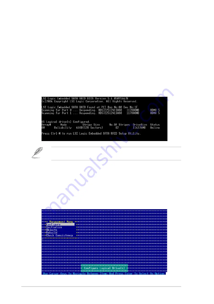
2.

During POST, the LSI Logic Embedded SATA RAID Setup Utility
automatically detects the installed SATA hard disk drives and displays
any existing RAID set(s). Press <Ctrl> + <M> to enter the utility.

The LSI Logic Embedded SATA RAID auto configures to RAID 1 when the
SATA to RAID Mode is enabled.

Содержание DSBF-D

Страница 1: ...Motherboard DSBF D Series DSBF D SAS DSBF D SAS DSBF D SAS DSBF D SAS DSBF D SAS DSBF D 1U DSBF D 1U DSBF D 1U DSBF D 1U DSBF D 1U DSBF D DSBF D DSBF D DSBF D DSBF D ...

Страница 2: ...uct is defaced or missing ASUS PROVIDES THIS MANUAL AS IS WITHOUT WARRANTY OF ANY KIND EITHER EXPRESS OR IMPLIED INCLUDING BUT NOT LIMITED TO THE IMPLIED WARRANTIES OR CONDITIONS OF MERCHANTABILITY OR FITNESS FOR A PARTICULAR PURPOSE IN NO EVENT SHALL ASUS ITS DIRECTORS OFFICERS EMPLOYEES OR AGENTS BE LIABLE FOR ANY INDIRECT SPECIAL INCIDENTAL OR CONSEQUENTIAL DAMAGES INCLUDING DAMAGES FOR LOSS OF...

Страница 3: ... 2 2 1 Placement direction 2 2 2 2 2 Screw holes 2 2 2 2 3 Support kits for the motherboard 2 3 2 2 4 Motherboard layouts 2 6 2 2 5 Layout contents 2 9 2 3 Central Processing Unit CPU 2 11 2 3 1 Installing the CPU 2 11 2 3 2 Installing the CPU heatsink and fan 2 14 2 4 System memory 2 16 2 4 1 Overview 2 16 2 4 2 Memory configurations 2 16 2 4 3 Memory mirroring and sparing technology 2 18 2 4 4 I...

Страница 4: ... Creating a bootable floppy disk 4 1 4 1 2 Updating the BIOS using the Phoenix Phlash16 Utility 4 2 4 1 3 ASUS CrashFree BIOS 2 utility 4 3 4 1 4 ASUS Update utility 4 5 4 2 BIOS setup program 4 8 4 2 1 BIOS menu screen 4 9 4 2 2 Menu bar 4 9 4 2 3 Legend bar 4 10 4 2 4 Menu items 4 10 4 2 5 Sub menu items 4 10 4 2 6 Configuration fields 4 10 4 2 7 Pop up window 4 11 4 2 8 General help 4 11 4 3 Ma...

Страница 5: ...lities 5 3 5 2 LSI Logic Embedded SATA RAID Setup Utility 5 4 5 2 1 Creating a RAID 0 or RAID 1 set 5 5 5 2 2 Creating a RAID 10 set 5 11 5 2 3 Adding or viewing a RAID configuration 5 15 5 2 4 Initializing the logical drives 5 18 5 2 5 Rebuilding failed drives 5 23 5 2 6 Checking the drives for data consistency 5 25 5 2 7 Deleting a RAID configuration 5 28 5 2 8 Selecting the boot drive from a RA...

Страница 6: ... Driver installation 6 1 RAID driver installation 6 1 6 1 1 Creating a RAID driver disk 6 1 6 1 2 Installing the RAID controller driver 6 2 6 2 LAN driver installation 6 11 6 2 1 Windows 2000 Server 2003 6 11 6 2 2 Red Hat SuSE Linux 6 15 6 3 VGA driver installation 6 16 6 3 1 Windows 2000 Server 2003 6 16 Appendix Appendix Appendix Appendix Appendix Block diagrams Block diagrams Block diagrams Bl...

Страница 7: ...e user is encouraged to try to correct the interference by one or more of the following measures Reorient or relocate the receiving antenna Increase the separation between the equipment and receiver Connect the equipment to an outlet on a circuit different from that to which the receiver is connected Consult the dealer or an experienced radio TV technician for help Canadian Department of Communica...

Страница 8: ... correct voltage in your area If you are not sure about the voltage of the electrical outlet you are using contact your local power company If the power supply is broken do not try to fix it by yourself Contact a qualified service technician or your retailer Operation safety Operation safety Operation safety Operation safety Operation safety Before installing the motherboard and adding devices on ...

Страница 9: ...e also provided Chapter 5 RAID configuration Chapter 5 RAID configuration Chapter 5 RAID configuration Chapter 5 RAID configuration Chapter 5 RAID configuration This chapter provides instructions for setting up creating and configuring RAID sets using the available utilities Chapter 6 Driver installation Chapter 6 Driver installation Chapter 6 Driver installation Chapter 6 Driver installation Chap...

Страница 10: ... or Return key Key1 Key2 Key3 If you must press two or more keys simultaneously the key names are linked with a plus sign Example Ctrl Alt D Command Means that you must type the command exactly as shown then supply the required item or value enclosed in brackets Example At the DOS prompt type the command line format A S DANGER WARNING DANGER WARNING DANGER WARNING DANGER WARNING DANGER WARNING Inf...

Страница 11: ...s 256 MB up to 32 GB system memory Supports Memory Sparing and Mirroring Technology DSBF D DSBF D DSBF D DSBF D DSBF D 1 x PCI Express x16 slot x8 link Supports 1U riser 1 x PCI Express x8 slot x8 link Supports 2U riser 3 x PCI X 133 100 66 MHz 1 x PCI 33MHz 32 bits 5V slot 1 x DDR2 SO DIMM socket for ASUS server management card 3 Series DSBF D SAS DSBF D SAS DSBF D SAS DSBF D SAS DSBF D SAS 1 x P...

Страница 12: ...SI MegaRAID controller with RAID 0 RAID 1 and RAID 0 1 configuration DSBF D and DSBF D 1U model only DSBF D SAS model only LSI1068 PCI X SAS controller supports 2 x Serial Attached SCSI SAS channels each channel supports 4 HDDs with RAID 0 RAID 1 and RAID 1E configuration Zero Channel RAID optional ATI ES1000 PCI display controller Supports 16 MB display memory Intel 82563EB Network Connection Dua...

Страница 13: ...connector 10 1 pin 1 x Serial port connector 10 1 pin COM2 1 x Power supply SMBus connector 1 x Parallel port connector 26 1 pin LPT1 1 x System panel connector 20 pin PANEL1 1 x Auxiliary panel connector 1 x Serial General Purpose Input Output SGPIO connector for LSI MegaRAID SATA LED 6 1 pin SGPIO1 1 x SAS LSI1068 ports LED 18 1 pin SASLED1 1 x LPC connector for LPC debug cards 1 x SMBus header ...

Страница 14: ...x i v x i v x i v x i v x i v ...

Страница 15: ...1 Product introduction This chapter describes the motherboard features and the new technologies it supports ...

Страница 16: ...ASUS DSBF D Series ASUS DSBF D Series ASUS DSBF D Series ASUS DSBF D Series ASUS DSBF D Series Chapter summary 1 1 1 Welcome 1 1 1 2 Package contents 1 1 1 3 Special features 1 2 ...

Страница 17: ...e for the following items Motherboard Motherboard Motherboard Motherboard Motherboard D S B F D D S B F D D S B F D D S B F D D S B F D DSBF D SAS DSBF D SAS DSBF D SAS DSBF D SAS DSBF D SAS DSBF D 1U DSBF D 1U DSBF D 1U DSBF D 1U DSBF D 1U C a b l e s C a b l e s C a b l e s C a b l e s C a b l e s Serial ATA signal cables 6 6 6 Serial ATA power cable dual plug 3 3 3 Mini SAS cable 2 80 conductor...

Страница 18: ...e MCH provides the processor quadri channel FB DIMM memory support and PCI Express interfaces The Intel 6321ESB is a new generation server class I O controller hub that provides the interface for PCI 2 3 PCI Express and PCIX Intel Intel Intel Intel Intel EM64T EM64T EM64T EM64T EM64T The motherboard supports Intel processors with the Intel EM64T Extended Memory 64 Technology The Intel EM64T featur...

Страница 19: ...a320 SCSI technology See page 2 34 for the location of the SAS connectors Zero Channel RAID ZCR solution Zero Channel RAID ZCR solution Zero Channel RAID ZCR solution Zero Channel RAID ZCR solution Zero Channel RAID ZCR solution DSBF D SAS model only DSBF D SAS model only DSBF D SAS model only DSBF D SAS model only DSBF D SAS model only The motherboard comes with a ZCR socket for an optional Zero ...

Страница 20: ...educed voltage requirements See page 2 33 for details USB 2 0 technology USB 2 0 technology USB 2 0 technology USB 2 0 technology USB 2 0 technology The motherboard implements the Universal Serial Bus USB 2 0 specification dramatically increasing the connection speed from the 12 Mbps bandwidth on USB 1 1 to a fast 480 Mbps on USB 2 0 USB 2 0 is backward compatible with USB 1 1 See pages 2 31 and 2...

Страница 21: ...chnology ASUS Smart Fan technology ASUS Smart Fan technology ASUS Smart Fan technology ASUS Smart Fan technology The ASUS Smart Fan technology smartly adjusts the fan speeds according to the system loading to ensure quiet cool and efficient operation See page 4 29 for details ASUS MyLogo2 ASUS MyLogo2 ASUS MyLogo2 ASUS MyLogo2 ASUS MyLogo2 This new feature present in the motherboard allows you to ...

Страница 22: ...1 6 1 6 1 6 1 6 1 6 Chapter 1 Product introduction Chapter 1 Product introduction Chapter 1 Product introduction Chapter 1 Product introduction Chapter 1 Product introduction ...

Страница 23: ... Hardware information This chapter lists the hardware setup procedures that you have to perform when installing system components It includes description of the jumpers and connectors on the motherboard ...

Страница 24: ...ries ASUS DSBF D Series ASUS DSBF D Series Chapter summary 2 2 1 Before you proceed 2 1 2 2 Motherboard overview 2 2 2 3 Central Processing Unit CPU 2 11 2 4 System memory 2 16 2 5 Expansion slots 2 26 2 6 Jumpers 2 30 2 7 Switch 2 35 2 8 Connectors 2 36 ...

Страница 25: ...tatic pad or in the bag that came with the component Before you install or remove any component ensure Before you install or remove any component ensure Before you install or remove any component ensure Before you install or remove any component ensure Before you install or remove any component ensure that the power supply is switched off or the power that the power supply is switched off or the p...

Страница 26: ...lacement direction When installing the motherboard make sure that you place it into the chassis in the correct orientation The edge with external ports goes to the rear part of the chassis as indicated in the image below 2 2 2 2 2 2 2 2 2 2 2 2 2 2 2 Screw holes Screw holes Screw holes Screw holes Screw holes Place nine 9 screws into the holes indicated by circles to secure the motherboard to the ...

Страница 27: ...nstall the CEK spring 1 Locate the CPU heatsink holes on the motherboard 2 Position the CEK spring underneath the motherboard then match the CEK spring hooks to the CPU1 heatsink holes Heatsink hole Heatsink hole Heatsink hole Heatsink hole Heatsink hole Socket for CPU2 Socket for CPU2 Socket for CPU2 Socket for CPU2 Socket for CPU2 Socket for CPU1 Socket for CPU1 Socket for CPU1 Socket for CPU1 S...

Страница 28: ... to the lower CPU heatsink holes until they snap in place 5 If you installed a second CPU repeat steps 2 to 4 to install the CEK spring to the CPU2 heatsink holes The CEK springs appear as shown when installed CEK spring screw hole CEK spring screw hole CEK spring screw hole CEK spring screw hole CEK spring screw hole 3 Press the upper spring hooks inward then insert to the upper CPU heatsink hole...

Страница 29: ...he CEK spring screw holes otherwise you can not install the CPU heatsinks properly 7 Install the motherboard with the external I O ports toward the chassis rear panel The CPU sockets should be right on top of their respective standoffs Standoffs for CPU1 Standoffs for CPU1 Standoffs for CPU1 Standoffs for CPU1 Standoffs for CPU1 Standoffs for CPU2 Standoffs for CPU2 Standoffs for CPU2 Standoffs fo...

Страница 30: ...rd USB1 USB2 RJ 45 LAN 1 RJ 45 LAN 2 ATX12V1 CPU_FAN1 Intel 6321ESB Intel 5000P PSUSMB1 BPSMB1 LSI SAS1068 AUX_PANEL1 HDLED1 USB34 USBPW34 LAN_BW1 LPT1 REAR_FAN1 USBPW12 DSBF D SAS ASMB3 Intel 6702PXHV PCIE1 DDR FB DIMM_31 64 72 bit 240 pin module DDR FB DIMM_20 64 72 bit 240 pin module DDR FB DIMM_21 64 72 bit 240 pin module DDR FB DIMM_10 64 72 bit 240 pin module DDR FB DIMM_11 64 72 bit 240 pin...

Страница 31: ... 5000P PSUSMB1 BPSMB1 AUX_PANEL1 HDLED1 USB34 USBPW34 LAN_BW1 LPT1 REAR_FAN1 USBPW12 DSBF D 1U ASMB3 PCIE1 DDR FB DIMM_31 64 72 bit 240 pin module DDR FB DIMM_20 64 72 bit 240 pin module DDR FB DIMM_21 64 72 bit 240 pin module DDR FB DIMM_10 64 72 bit 240 pin module DDR FB DIMM_11 64 72 bit 240 pin module DDR FB DIMM_00 64 72 bit 240 pin module DDR FB DIMM_01 64 72 bit 240 pin module 33cm 13in 30 ...

Страница 32: ...21ESB Intel 5000P PSUSMB1 BPSMB1 AUX_PANEL1 HDLED1 USB34 USBPW34 LAN_BW1 LPT1 REAR_FAN1 USBPW12 DSBF D ASMB3 Intel 6702PXHV PCIE1 DDR FB DIMM_31 64 72 bit 240 pin module DDR FB DIMM_20 64 72 bit 240 pin module DDR FB DIMM_21 64 72 bit 240 pin module DDR FB DIMM_10 64 72 bit 240 pin module DDR FB DIMM_11 64 72 bit 240 pin module DDR FB DIMM_00 64 72 bit 240 pin module DDR FB DIMM_01 64 72 bit 240 p...

Страница 33: ...PCI Express x16 slot 2 29 Jumpers Jumpers Jumpers Jumpers Jumpers P a g e P a g e P a g e P a g e P a g e 1 Clear RTC RAM CLRTC1 2 30 2 LAN bandwidth setting 3 pin LAN_BW1 2 31 3 USB device wake up 3 pin USBPW12 USBPW34 2 31 4 Keyboard power 3 pin KBPWR1 2 32 5 VGA controller setting 3 pin VGA_EN1 2 32 6 LAN controller setting 3 pin LAN1_EN1 2 33 7 Intel 6321ESB SATA port S W RAID setting 3 pin RA...

Страница 34: ...onnectors 4 pin CPU_FAN1 2 2 41 REAR_FAN1 2 FRNT_FAN1 2 3 4 FBD_FAN1 9 Power supply SMBus connector 5 pin PSUSMB1 2 41 10 SSI power connectors 24 pin ATXPWR1 8 pin ATX12V1 2 42 4 pin ATX12V2 11 Parallel port connector 26 1 pin LPT1 2 43 12 Backplane SMBus connector 6 1 pin BPSMB1 2 43 13 SAS LSI1068 ports LED connector 18 1 pin SASLED1 2 44 DSBF D SAS model only 14 Serial General Purpose Input Out...

Страница 35: ... for the CPU and heatsink If the instructions in this section do not match the CPU documentation follow the latter Upon purchase of the motherboard make sure that the PnP cap is on the socket and the socket contacts are not bent Contact your retailer immediately if the PnP cap is missing or if you see any damage to the PnP cap socket contacts motherboard components ASUS will shoulder the cost of r...

Страница 36: ...ocket alignment key should fit into the CPU notch Gold triangle mark Gold triangle mark Gold triangle mark Gold triangle mark Gold triangle mark Load plate Load plate Load plate Load plate Load plate A B 2 Press the load lever with your thumb A then move it to the left B until it is released from the retention tab Retention tab Retention tab Retention tab Retention tab Retention tab Load lever Loa...

Страница 37: ...talling Windows 2003 Server or later version is recommended Make sure to enable the Hyper Threading Technology item in BIOS before installing a supported operating system The amount of CPU threads depends on the OS support For more information on Hyper Threading Technology visit www intel com info hyperthreading To use the Hyper Threading Technology on this motherboard 1 Install an Intel Xeon CPU ...

Страница 38: ...stalling the CPU heatsink and fan Make sure that you have applied the thermal grease to the top of the CPU before installing the heatsink and fan Refer to the installation manual that came with the CPU package for details on heatsink fan assembly and installation To install the CPU heatsink and fan 1 Place the heatsink on top of the installed CPU making sure that the four screws on the heatsink al...

Страница 39: ...ug this connector 2 Use a Phillips screwdriver to tighten the four heatsink screws in a diagonal sequence 3 Connect the fan cable to the 4 pin connector labeled CPU_FAN1 4 Repeat steps 1 to 3 to install the other heatsink if you have installed a second CPU then connect the fan cable to the 4 pin connector labeled CPU_FAN2 CPU_FAN1 CPU_FAN1 CPU_FAN1 CPU_FAN1 CPU_FAN1 connector connector connector c...

Страница 40: ...figure illustrates the location of the FB DIMM sockets 2 4 2 2 4 2 2 4 2 2 4 2 2 4 2 Memory configurations Memory configurations Memory configurations Memory configurations Memory configurations You may install 256 MB 512 MB 1 GB 2 GB and 4 GB registered ECC FB DIMMs into the DIMM sockets For optimum compatibility we recommend that you obtain memory modules from the same vendor Refer to the Qualif...

Страница 41: ...IMM_30 DIMM_01 DIMM_11 DIMM_21 DIMM_31 D I M M 3 1 D I M M 3 1 D I M M 3 1 D I M M 3 1 D I M M 3 1 D I M M 3 0 D I M M 3 0 D I M M 3 0 D I M M 3 0 D I M M 3 0 D I M M 2 1 D I M M 2 1 D I M M 2 1 D I M M 2 1 D I M M 2 1 D I M M 2 0 D I M M 2 0 D I M M 2 0 D I M M 2 0 D I M M 2 0 D I M M 1 1 D I M M 1 1 D I M M 1 1 D I M M 1 1 D I M M 1 1 D I M M 1 0 D I M M 1 0 D I M M 1 0 D I M M 1 0 D I M M 1 0 D...

Страница 42: ...nstalled memories memories memories memories memories The below two memory configurations were required to operate in mirrored mode 1 Configuration 1 Mirroring Four memories population Four memories population Four memories population Four memories population Four memories population D I M M 0 0 S l o t 0 C h a n n e l 0 D I M M 0 0 S l o t 0 C h a n n e l 0 D I M M 0 0 S l o t 0 C h a n n e l 0 D...

Страница 43: ...l memories size will also reduce the largest ranks size in the channel 0 or 1 of the Branch 0 Rank Sparing in the Branch 0 only supports 4 6 8 memory populations as the below table D I M M 0 0 S l o t 0 C h a n n e l 0 D I M M 0 0 S l o t 0 C h a n n e l 0 D I M M 0 0 S l o t 0 C h a n n e l 0 D I M M 0 0 S l o t 0 C h a n n e l 0 D I M M 0 0 S l o t 0 C h a n n e l 0 MCH MCH MCH MCH MCH Branch 0 ...

Страница 44: ...so reduce the largest ranks size in the channel 2 or 3 of the Branch 1 Rank Sparing in the Branch 1 only supports 4 and 8 memory populations as the below table Number of DIMMs 4 6 8 Memory slot s to use Branch 1 Channel 3 DIMM 31 V DIMM 30 V Channel 2 DIMM 21 V V DIMM 20 V V Branch 0 Channel 1 DIMM 11 V V V Enable Sparing DIMM 10 V V V Channel 0 DIMM 01 V V V DIMM 00 V V V Number of DIMMs 4 8 Memo...

Страница 45: ...l 0 or 1 of the Branch 0 and channel 3 or 4 of the Branch 1 and assign as the sparing DIMMs The total memories size will also reduce the two sparing DIMMs size Rank Sparing in the Branch 1 and 0 only supports 8 memory populations as the below table Number of DIMMs 8 Memory slot s to use Branch 1 Channel 3 DIMM 31 V Enable Sparing DIMM 30 V Channel 2 DIMM 21 V DIMM 20 V Branch 0 Channel 1 DIMM 11 V...

Страница 46: ...e break on the socket 3 Firmly insert the DIMM into the socket until the retaining clips snap back in place and the DIMM is properly seated 2 4 5 2 4 5 2 4 5 2 4 5 2 4 5 Removing a DIMM Removing a DIMM Removing a DIMM Removing a DIMM Removing a DIMM To remove a DIMM 1 Simultaneously press the retaining clips outward to unlock the DIMM 2 Remove the DIMM from the socket A DDR2 DIMM is keyed with a n...

Страница 47: ...ng the optional MemCool FB DIMM fan 2 Disengage the fan top cover from the fan base You can do this by firmly gripping the top cover by the clamps to release the hooks then pull up the top cover carefully until it separates from the fan base T o p T o p T o p T o p T o p c o v e r c o v e r c o v e r c o v e r c o v e r h o o k h o o k h o o k h o o k h o o k Top cover Top cover Top cover Top cove...

Страница 48: ...ter 2 Hardware information 5 Connect the fan cable to the 4 pin connector labeled FB_DIMM1 4 Position top cover over the fan base Insert the top cover legs into the slot on the fan base legs Push down carefully until the legs are securely in place and the top cover hooks snap in place Make sure the cables pass through the notch on the fan base as shown ...

Страница 49: ...FB DIMM fan nstalling the optional MemCool FB DIMM fan nstalling the optional MemCool FB DIMM fan nstalling the optional MemCool FB DIMM fan 1 Unplug the fan cable 2 Grip the top cover clamps until the top cover hooks are released then carefully lift the top cover while supporting the fan base with your free hand Top cover Top cover Top cover Top cover Top cover c l a m p c l a m p c l a m p c l a...

Страница 50: ... connector with the slot and press firmly until the card is completely seated on the slot 5 Secure the card to the chassis with the screw you removed earlier 6 Replace the system cover 2 5 2 2 5 2 2 5 2 2 5 2 2 5 2 Configuring an expansion card Configuring an expansion card Configuring an expansion card Configuring an expansion card Configuring an expansion card After installing the expansion card...

Страница 51: ...R Q Priority Priority Priority Priority Priority Standard Function Standard Function Standard Function Standard Function Standard Function 0 1 System Timer 1 2 Keyboard Controller 2 Re direct to IRQ 9 3 11 Communications Port COM2 4 12 Communications Port COM1 5 13 IRQ holder for PCI steering 6 14 Floppy Disk Controller 7 15 Printer Port LPT1 8 3 System CMOS Real Time Clock 9 4 IRQ holder for PCI ...

Страница 52: ... socket DDR2 SO DIMM socket DDR2 SO DIMM socket DDR2 SO DIMM socket DDR2 SO DIMM socket 2 5 4 2 5 4 2 5 4 2 5 4 2 5 4 PCI PCI X slots PCI PCI X slots PCI PCI X slots PCI PCI X slots PCI PCI X slots The PCI PCI X slots support cards such as a LAN card SCSI card USB card and other cards that comply with PCI 2 3 and PCI X 1 0 specifications The figure shows a LAN card installed on a PCI slot 32 bit P...

Страница 53: ...slot PCI Express x8 slot When installing an optional ZCR card install the card on PCIX6 slot colored green on DSBF D SAS model 2 5 7 2 5 7 2 5 7 2 5 7 2 5 7 PCI Express x16 slot x8 link PCI Express x16 slot x8 link PCI Express x16 slot x8 link PCI Express x16 slot x8 link PCI Express x16 slot x8 link This motherboard supports PCI Express cards that comply with the PCI Express specifications PCI Ex...

Страница 54: ...OS You can clear the CMOS memory of date time and system setup parameters by erasing the CMOS RTC RAM data The onboard button cell battery powers the RAM data in CMOS which include system setup information such as system passwords To erase the RTC RAM 1 Turn OFF the computer and unplug the power cord 2 Remove the onboard battery 3 Move the jumper cap from pins 1 2 default to pins 2 3 Keep the cap ...

Страница 55: ...ires a power supply that can provide 500mA on the 5VSB lead for each USB port otherwise the system will not power up If you are using Windows 2000 you need to install Service Pack 4 to wake up the system from S4 sleep mode The total current consumed must NOT exceed the power supply capability 5VSB whether under normal condition or in sleep mode 2 2 2 2 2 LAN bandwidth setting 3 pin LAN_BW1 LAN ban...

Страница 56: ...hen you press a key on the keyboard the default is the Space Bar This feature requires an ATX power supply that can supply at least 1A on the 5VSB lead and a corresponding setting in the BIOS 5 5 5 5 5 VGA controller setting 3 pin VGA_EN1 VGA controller setting 3 pin VGA_EN1 VGA controller setting 3 pin VGA_EN1 VGA controller setting 3 pin VGA_EN1 VGA controller setting 3 pin VGA_EN1 These jumpers...

Страница 57: ...ATA port S W RAID setting 6321ESB SATA port S W RAID setting 6321ESB SATA port S W RAID setting 3 pin RAID_SEL1 3 pin RAID_SEL1 3 pin RAID_SEL1 3 pin RAID_SEL1 3 pin RAID_SEL1 DSBF D and DSBF D 1U models only This jumper allows you to select the Serial ATA RAID configuration utility to use when you create disk arrays Both utilities are supported by the Intel 6321ESB Place the jumper caps on pins 1...

Страница 58: ...BIOS recovery setting 3 pin RECOVERY1 Force BIOS recovery setting 3 pin RECOVERY1 Force BIOS recovery setting 3 pin RECOVERY1 Force BIOS recovery setting 3 pin RECOVERY1 This jumper allows you to quickly update or recover the BIOS settings when it becomes corrupted To update the BIOS 1 Prepare an emergent BIOS Recovery floppy disk which is created via the support CD Refer to 4 1 3 for details 2 Se...

Страница 59: ...ector 1 CPU_FAN1 2 CPU_FAN1 3 FRNT_FAN1 4 FRNT_FAN2 5 FRNT_FAN3 6 FRNT_FAN4 7 REAR_FAN1 8 REAR_FAN2 If you use a 4 pin fan but set the DIP switch for a 3 pin fan the fan you installed may not work If you use a 3 pin fan but set the DIP switch for a 4 pin fan the fan controll will not work and the fan you installed will always run at full speed DSBF D Series DSBF D Series DIP switches DIP_SW1 ON 4 ...

Страница 60: ...D ACT LINK ACT LINK ACT LINK ACT LINK ACT LINK L E D L E D L E D L E D L E D 1 1 1 1 1 PS 2 mouse port green PS 2 mouse port green PS 2 mouse port green PS 2 mouse port green PS 2 mouse port green This port is for a PS 2 mouse 2 2 2 2 2 PS 2 keyboard port purple PS 2 keyboard port purple PS 2 keyboard port purple PS 2 keyboard port purple PS 2 keyboard port purple This port is for a PS 2 keyboard ...

Страница 61: ...ctors Internal connectors Internal connectors Internal connectors Internal connectors 1 1 1 1 1 Floppy disk drive connector 34 1 pin FLOPPY1 Floppy disk drive connector 34 1 pin FLOPPY1 Floppy disk drive connector 34 1 pin FLOPPY1 Floppy disk drive connector 34 1 pin FLOPPY1 Floppy disk drive connector 34 1 pin FLOPPY1 This connector is for the provided floppy disk drive FDD signal cable Insert on...

Страница 62: ...D connector 4 pin HDLED1 Hard disk activity LED connector 4 pin HDLED1 Hard disk activity LED connector 4 pin HDLED1 Hard disk activity LED connector 4 pin HDLED1 Hard disk activity LED connector 4 pin HDLED1 This connector is used to connect to a hard disk drive active LED connector on the SCSI or RAID card DSBF D Series DSBF D Series storage card activity LED connector HDLED1 1 ADD_IN_CARD NC NC...

Страница 63: ...with two Serial Attached SCSI SAS connectors the next generation storage technology that supports both Serial Attached SCSI and Serial ATA Each connector supports up to four 4 devices To connect the mini SAS cable Plug in the mini SAS cable to the mini SAS connector until the cable lock snaps in place To disconnect the mini SAS cable 1 With your thumb push down the cable lock to release 2 While st...

Страница 64: ...the back of the system chassis The serial port module is purchased separately 6 6 6 6 6 USB connector 10 1 pin USB34 USB connector 10 1 pin USB34 USB connector 10 1 pin USB34 USB connector 10 1 pin USB34 USB connector 10 1 pin USB34 This connector is for USB 2 0 ports Connect the USB module cable to this connector then install the module to a slot opening at the back of the system chassis This USB...

Страница 65: ...board components These are not jumpers Do not place jumper caps on the fan connectors See section 2 7 Switch for DIP switch settings for 4 pin and 3 pin fan cables 9 9 9 9 9 Power supply SMBus connector 5 pin PSUSMB1 Power supply SMBus connector 5 pin PSUSMB1 Power supply SMBus connector 5 pin PSUSMB1 Power supply SMBus connector 5 pin PSUSMB1 Power supply SMBus connector 5 pin PSUSMB1 This connec...

Страница 66: ...ors completely fit For a fully configured system we recommend that you use an SSI 12 V compliant power supply unit PSU for LGA771 socket Intel Xeon Dual Core processors Bensley platform Do not forget to connect the 24 8 4 pin power plugs otherwise the system will not boot up Use of a PSU with a higher power output is recommended when configuring a system with more power consuming devices The syste...

Страница 67: ...of the system chassis DSBF D Series DSBF D Series Parallel port connector LPT1 SPD7 GND SPD6 GND SPD5 GND SPD4 GND SLCT PE GND BUSY ACK GND SPD3 GND SPD2 SLIN SPD1 PINIT SPD0 ERROR STB AFD GND Pin 1 12 12 12 12 12 Backplane SMBus Backplane SMBus Backplane SMBus Backplane SMBus Backplane SMBus connector connector connector connector connector 6 1 6 1 6 1 6 1 6 1 pin pin pin pin pin BPSMB1 BPSMB1 BP...

Страница 68: ...s DSBF D Series SASLED connector SASLED1 ACT_LED0 FLT_LED0 1 ACT_LED1 FLT_LED1 ACT_LED2 FLT_LED2 ACT_LED3 FLT_LED3 ACT_LED4 GND ACT_LED5 FLT_LED4 FLT_LED5 ACT_LED6 FLT_LED6 ACT_LED7 FLT_LED7 14 14 14 14 14 Serial General Purpose Input Output Serial General Purpose Input Output Serial General Purpose Input Output Serial General Purpose Input Output Serial General Purpose Input Output connector conn...

Страница 69: ...IDE_LED Hard disk drive activity LED Red 2 pin IDE_LED This 2 pin connector is for the HDD Activity LED Connect the HDD Activity LED cable to this connector The IDE LED lights up or flashes when data is read from or written to the HDD System warning speaker Orange 4 pin SPEAKER System warning speaker Orange 4 pin SPEAKER System warning speaker Orange 4 pin SPEAKER System warning speaker Orange 4 p...

Страница 70: ...pin connectors are for the LAN1 and LAN2 Activity LED Connect the LAN Activity LED cable to this connector This LED blinks during a network activity and is always lit when linked 3 3 3 3 3 Chassis Intrusion connector 4 1pin CASEOPEN Chassis Intrusion connector 4 1pin CASEOPEN Chassis Intrusion connector 4 1pin CASEOPEN Chassis Intrusion connector 4 1pin CASEOPEN Chassis Intrusion connector 4 1pin ...

Страница 71: ...3 Powering up This chapter describes the power up sequence and ways of shutting down the system ...

Страница 72: ...ASUS DSBF D Series ASUS DSBF D Series ASUS DSBF D Series ASUS DSBF D Series ASUS DSBF D Series Chapter summary 3 3 1 Starting up for the first time 3 1 3 2 Turning off the computer 3 2 ...

Страница 73: ... power standby feature the monitor LED may light up or switch between orange and green after the system LED turns on The system then runs the power on self tests or POST While the tests are running the BIOS beeps see BIOS beep codes table below or additional messages appear on the screen If you do not see anything within 60 seconds from the time you turned on the power the system may have failed a...

Страница 74: ...pply should turn off after Windows shuts down If you are using Windows XP 1 Click the Start Start Start Start Start button then select Turn Off Computer Turn Off Computer Turn Off Computer Turn Off Computer Turn Off Computer 2 Click the Turn Off Turn Off Turn Off Turn Off Turn Off button to shut down the computer 3 The power supply should turn off after Windows shuts down 3 2 2 3 2 2 3 2 2 3 2 2 3...

Страница 75: ...4 BIOS setup This chapter tells how to change the system settings through the BIOS Setup menus Detailed descriptions of the BIOS parameters are also provided ...

Страница 76: ...ries ASUS DSBF D Series ASUS DSBF D Series ASUS DSBF D Series 4 1 Managing and updating your BIOS 4 1 4 2 BIOS setup program 4 8 4 3 Main menu 4 12 4 4 Advanced menu 4 17 4 5 Server menu 4 30 4 6 Security menu 4 32 4 7 Boot menu 4 34 4 7 Exit menu 4 36 ...

Страница 77: ... into the drive b At the DOS prompt type format A S then press Enter Windows XP environment a Insert a 1 44 MB floppy disk to the floppy disk drive b Click Start Start Start Start Start from the Windows desktop then select M y M y M y M y M y Computer Computer Computer Computer Computer c Select the 3 1 2 Floppy Drive icon d Click File File File File File from the menu then select Format Format Fo...

Страница 78: ...f the support CD to the floppy disk with the latest BIOS file 3 Boot the system in DOS mode using the bootable floppy disk you created earlier 4 After posting and reading the boot data from floppy press F5 to bypass some unnecessary files 5 When the A A A A A appears replace the bootable floppy disk with the floppy disk containing the new BIOS file and the Phoenix Phlash16 Utility 6 At the prompt ...

Страница 79: ...he BIOS from the support CD and a floppy disk 1 Insert the support CD and a floppy disk to a PC then boot from the support CD the screen will show several optional items 2 Select the item Create the emergent BIOS Recovery diskette 3 After the floppy disk is created put this disk in the floppy disk drive then turn on the machine 4 The utility displays the following message and automatically checks ...

Страница 80: ...THEN ON Flash part SST49LF008A DeviceID 5a Mfr ID bf Ready to restart the system 00 00 00 1E DO NOT shut down or reset the system while updating the BIOS Doing so can cause system boot failure Phoenix Phlash16 Utility Version 1 6 1 9 Copyright c Phoenix Technologies Ltd 2005 Performing the following function Load Image File BIOS WPH Verify interface information Backup system BIOS ROM Check flash m...

Страница 81: ...y ASUS Update utility ASUS Update utility ASUS Update utility The ASUS Update is a utility that allows you to manage save and update the motherboard BIOS in Windows environment The ASUS Update utility allows you to Save the current BIOS file Download the latest BIOS file from the Internet Update the BIOS from an updated BIOS file Update the BIOS directly from the Internet and View the BIOS version...

Страница 82: ...the Internet Updating the BIOS through the Internet To update the BIOS through the Internet 1 Launch the ASUS Update utility from the Windows desktop by clicking Start Start Start Start Start Programs Programs Programs Programs Programs ASUS ASUS ASUS ASUS ASUS ASUSUpdate ASUSUpdate ASUSUpdate ASUSUpdate ASUSUpdate ASUSUpdate ASUSUpdate ASUSUpdate ASUSUpdate ASUSUpdate The ASUS Update main window ...

Страница 83: ...te ASUSUpdate ASUSUpdate ASUSUpdate ASUSUpdate ASUSUpdate ASUSUpdate The ASUS Update main window appears 2 Select Update BIOS from a Update BIOS from a Update BIOS from a Update BIOS from a Update BIOS from a file file file file file option from the drop down menu then click Next Next Next Next Next 4 From the FTP site select the BIOS version that you wish to download Click Next Next Next Next Nex...

Страница 84: ... Press Del during the Power On Self Test POST to enter the Setup utility otherwise POST continues with its test routines If you wish to enter Setup after POST restart the system by pressing Ctrl Alt Delete or by pressing the reset button on the system chassis You can also restart by turning the system off and then back on Do this last option only if the first two failed The Setup program is design...

Страница 85: ...4 2 1 4 2 1 4 2 1 4 2 1 4 2 1 BIOS menu screen BIOS menu screen BIOS menu screen BIOS menu screen BIOS menu screen F1 Help Select Item Change Values F9 Setup Defaults ESC Exit Select Menu Enter Select Sub menu F10 Save and Exit PhoenixBIOS Setup Utility Main Advanced Server Security Boot Exit Item Specific Help Tab Shift Tab or Enter selects field System Date 04 19 2006 System Time 15 30 36 Floppy...

Страница 86: ...er to display a list of options Refer to 4 2 7 Pop up window 4 2 3 4 2 3 4 2 3 4 2 3 4 2 3 Legend bar Legend bar Legend bar Legend bar Legend bar At the bottom of the Setup screen is a legend bar The keys in the legend bar allow you to navigate through the various setup menus The following table lists the keys found in the legend bar with their corresponding functions Navigation Key Navigation Key...

Страница 87: ...nu screen is a brief description of the selected item F1 Help Select Item Change Values F9 Setup Defaults ESC Exit Select Menu Enter Select Sub menu F10 Save and Exit PhoenixBIOS Setup Utility Main Advanced Server Security Boot Exit Item Specific Help Tab Shift Tab or Enter selects field System Date 04 19 2006 System Time 15 30 36 Floppy A 1 44 1 25 MB 3 1 2 IDE Configuration IDE Channel 0 Master ...

Страница 88: ...4 3 3 4 3 3 4 3 3 Floppy A 1 44M 3 5 in Floppy A 1 44M 3 5 in Floppy A 1 44M 3 5 in Floppy A 1 44M 3 5 in Floppy A 1 44M 3 5 in Sets the type of floppy drive installed Configuration options Disabled 360 Kb 5 1 4 1 2 MB 5 1 4 720 Kb 3 1 2 1 44 1 25 MB 3 1 2 2 88 MB 3 1 2 Refer to section 5 2 1 BIOS menu screen for information on the menu screen items and how to navigate through them F1 Help Select ...

Страница 89: ...d disk boot sector Normal Setting this item to Write Protect prevents write access to the boot sector on the hard disk to protect against viruses The defaul setting Normal allows write access Configuration options Normal Write Protect S ATA Configuration S ATA Configuration S ATA Configuration S ATA Configuration S ATA Configuration F1 Help Select Item Change Values F9 Setup Defaults ESC Exit Sele...

Страница 90: ...placed in legacy mode SATA RAID Enable Disabled SATA RAID Enable Disabled SATA RAID Enable Disabled SATA RAID Enable Disabled SATA RAID Enable Disabled Allows you to enable or disable the Serial ATA RAID function Configuration options Disabled Enabled SATA AHCI Enable Disabled SATA AHCI Enable Disabled SATA AHCI Enable Disabled SATA AHCI Enable Disabled SATA AHCI Enable Disabled Allows you to enab...

Страница 91: ...device is either a ZIP LS 120 or MO drive Select User to manually enter the parameters of the device Configuration options Auto User CD ROM ATAPI Removable Muti Sector Transfers Disabled Muti Sector Transfers Disabled Muti Sector Transfers Disabled Muti Sector Transfers Disabled Muti Sector Transfers Disabled Enables or disables data multi sectors transfers When set to Auto the data transfer from ...

Страница 92: ...ifications The BIOS automatically detects the items in this menu F1 Help Select Item Change Values F9 Setup Defaults ESC Exit Select Menu Enter Select Sub menu F10 Save and Exit PhoenixBIOS Setup Utility Main Item Specific Help The detailed information for CPUs System Information Model Name ASUS DSBF D SAS Model ID 8012A0 ASUS BIOS Version 1000 021 Date 03 16 2006 Processor Information System Memo...

Страница 93: ...ction 4 4 1 4 4 1 4 4 1 4 4 1 4 4 1 Advanced Processor Options Advanced Processor Options Advanced Processor Options Advanced Processor Options Advanced Processor Options F1 Help Select Item Change Value F9 Setup Defaults ESC Exit Select Menu Enter Select Sub menu F10 Save and Exit Item Specific Help Configures the MP Specification revision level Advanced Processor Options Multiprocessor Specifica...

Страница 94: ...st String Operations Enabled Fast String Operations Enabled Fast String Operations Enabled Configuration options Disabled Enabled Compatible FPU Code Disabled Compatible FPU Code Disabled Compatible FPU Code Disabled Compatible FPU Code Disabled Compatible FPU Code Disabled Configuration options Disabled Enabled Split Lock Operations Enabled Split Lock Operations Enabled Split Lock Operations Enab...

Страница 95: ...nced x8 Detection Enabled Force ITK Config Clocking Disabled Enable Multimedia Timer No FBDIMM S Thermal Throttling Control Open Loop Open Loop Type Best Performan Memory Cache PhoenixBIOS Setup Utility Advanced Crystal Beach Configure Enable Enabled Crystal Beach Configure Enable Enabled Crystal Beach Configure Enable Enabled Crystal Beach Configure Enable Enabled Crystal Beach Configure Enable E...

Страница 96: ...orce ITK Config Clocking Disabled Force ITK Config Clocking Disabled Allows you to enable or disable the FBD configuration for ITK test suite Configuration options Disabled Enabled Enable Multimedia Timer No Enable Multimedia Timer No Enable Multimedia Timer No Enable Multimedia Timer No Enable Multimedia Timer No Allows you to enable Yes or disable No the multimedia timer support Configuration op...

Страница 97: ...E000 E3FF Write Protect Cache E400 E7FF Write Protect Cache E800 EBFF Write Protect Cache EC00 EFFF Write Protect PhoenixBIOS Setup Utility Advanced Cache System BIOS area Write Protect Controls caching of the system BIOS area Configuration options Uncached Write Protect Cache Video BIOS area Write Protect Controls caching of the video BIOS area Configuration options Uncached Write Protect Cache B...

Страница 98: ...D3FF Cache D400 D7FF Cache D800 DBFF Cache DC00 DFFF Cache E000 E3FF Cache E400 E7FF Cache E800 EBFF Cache EC00 EFFF Refer to the configuration options information below Disabled This block is not cached USWC Caching Uncached Speculative Write Combined Write Through Writes are cached and sent to main memory at once Write Protect Writes are ignored Write Back Writes are cached but not sent to memor...

Страница 99: ...he desired value ICH USB Control Sub Menu USB Device 29 All Functions Enabled USB Device 29 Function 7 Enabled Legacy USB Support Enabled PhoenixBIOS Setup Utility Advanced 4 4 4 4 4 4 4 4 4 4 4 4 4 4 4 ICH USB Control Sub Menu ICH USB Control Sub Menu ICH USB Control Sub Menu ICH USB Control Sub Menu ICH USB Control Sub Menu The items in this menu allow you to display the USB configuration settin...

Страница 100: ...ECP DMA channel DMA 3 Floppy disk controller Enabled PhoenixBIOS Setup Utility Advanced 4 4 5 4 4 5 4 4 5 4 4 5 4 4 5 Peripheral Devices Configuration Peripheral Devices Configuration Peripheral Devices Configuration Peripheral Devices Configuration Peripheral Devices Configuration This menu shows the peripheral devices configuration settings Select an item then press Enter to display the configur...

Страница 101: ...Configuration options Disabled Enabled Base I O address 378 Base I O address 378 Base I O address 378 Base I O address 378 Base I O address 378 Allows you to select the base I O address for the parallel port Configuration options 378 278 3BC Interrupt IRQ 7 Interrupt IRQ 7 Interrupt IRQ 7 Interrupt IRQ 7 Interrupt IRQ 7 Allows you to set the interrupt for the parallel port Configuration options IR...

Страница 102: ...erface ACPI configuration settings Select an item then press Enter to display the configuration options ACPI Version Features ACPI v1 0 ACPI Version Features ACPI v1 0 ACPI Version Features ACPI v1 0 ACPI Version Features ACPI v1 0 ACPI Version Features ACPI v1 0 Allows you to enable RSDP pointers to 64 bit fixed system description tables Configuration options ACPI v1 0 ACPI v2 0 ACPI v3 0 Headles...

Страница 103: ...ption When set to Power On the system turns on automatically after a power interruption When set to Last State the system goes into whatever was the system state on or off before the power interruption Configuration options Power Off Power On Last State Power Up By PS 2 Keyboard Disabled Power Up By PS 2 Keyboard Disabled Power Up By PS 2 Keyboard Disabled Power Up By PS 2 Keyboard Disabled Power ...

Страница 104: ...e 00 00 00 RTC Alarm Date 00 00 00 RTC Alarm Date 00 00 00 To set the time of alarm 1 Press or to set the desired value 2 Use the left right arrow key or press Tab to move to the next field 3 Press Enter when done F1 Help Select Item Change Value F9 Setup Defaults ESC Exit Select Menu Enter Select Sub menu F10 Save and Exit Item Specific Help When the current temperature equals this limit the fan ...

Страница 105: ...d REAR_FAN1 2 Speed REAR_FAN1 2 Speed REAR_FAN1 2 Speed REAR_FAN1 2 Speed These fields show the auto detected values and are not user configurable If no fan is installed the field shows 0 RPM Smart Fan Control Smart Fan II Smart Fan Control Smart Fan II Smart Fan Control Smart Fan II Smart Fan Control Smart Fan II Smart Fan Control Smart Fan II Allows you to disable or configure the Smart Fan feat...

Страница 106: ...customize the server features Com Port Address Disabled Com Port Address Disabled Com Port Address Disabled Com Port Address Disabled Com Port Address Disabled Allows you to disable or select the COM port to use Configuration options Disabled On board COM A On board COM B F1 Help Select Item Change Value F9 Setup Defaults ESC Exit Select Menu Enter Select Sub menu F10 Save and Exit Item Specific H...

Страница 107: ...o select the flow control for console redirection Configuration options None XON XOFF CTS RTS Console Connection Direct Console Connection Direct Console Connection Direct Console Connection Direct Console Connection Direct Allows you to select the console connection Direct indicates that the console is connected directed to the system Via modem indicates that a modem is used to connect Configurat...

Страница 108: ... log iew DMI event log Enter Enter Enter Enter Enter Allows you to view the conents of the DMI event log Event Logging Enabled Event Logging Enabled Event Logging Enabled Event Logging Enabled Event Logging Enabled Allows you to enable or disable logging of DMI events Configuration options Disabled Enabled ECC Event Logging Enabled ECC Event Logging Enabled ECC Event Logging Enabled ECC Event Logg...

Страница 109: ...Password Is Clear User Password Is Clear User Password Is Clear User Password Is Clear These fields allow you to set passwords To set a password 1 Select an item then press Enter 2 Type in a password using a combination of a maximum of eight 8 alpha numeric characters then press Enter 3 When prompted confirm the password by typing the exact characters again then press Enter The password field sett...

Страница 110: ...d Forgot your password If you forget your password you can clear it by erasing the CMOS Real Time Clock RTC RAM The RAM data containing the password information is powered by the onboard button cell battery If you need to erase the CMOS RAM refer to section 2 6 Jumpers for instructions Password Check Setup Password Check Setup Password Check Setup Password Check Setup Password Check Setup This fie...

Страница 111: ... x excludes or includes the device to boot Shift 1 enables or disables the device 1 4 Loads default boot sequence Boot Device Priority Boot priority order 1 Legacy floppy drives 2 IDE 3 XXXX drive 3 4 5 6 7 8 Excluded from boot order PCI BEV IBA GE Slot 0600 v1236 PCI BEV IBA GE Slot 0601 v1236 Legacy Network Card PhoenixBIOS Setup Utility Main Advanced Server Security Boot Exit 4 7 1 4 7 1 4 7 1 ...

Страница 112: ...OST items Configuration options Disabled Enabled Full Logo Display Enabled Full Logo Display Enabled Full Logo Display Enabled Full Logo Display Enabled Full Logo Display Enabled Allows you to enable or disable the full screen logo display feature Configuration options Disabled Enabled Set this item to Enabled to use the ASUS MyLogo2 feature Bootup Num Lock On Bootup Num Lock On Bootup Num Lock On...

Страница 113: ...n reboot system Save Changes and Exit Discard Changes and Exit Discard Changes Load Setup Defaults 4 8 Exit menu PhoenixBIOS Setup Utility Main Advanced Server Security Boot Exit Save Changes and Exit Save Changes and Exit Save Changes and Exit Save Changes and Exit Save Changes and Exit Select this option then press Enter or simply press F10 to save your changes to CMOS before exiting the Setup u...

Страница 114: ...nter to discard any changes and load the previously saved values select No then press Enter or simply press Esc to cancel the command and return to the Exit menu Load Setup Defaults Load Setup Defaults Load Setup Defaults Load Setup Defaults Load Setup Defaults Select this option then press Enter or simply press F9 to load the optimized values for each of the Setup menu items When a confirmation w...

Страница 115: ...5 RAID configuration This chapter provides instructions for setting up creating and configuring RAID sets using the available utilities ...

Страница 116: ... D Series ASUS DSBF D Series Chapter summary 5 5 1 Setting up RAID 5 1 5 2 LSI Logic Embedded SATA RAID Setup Utility 5 4 5 3 Intel Matrix Storage Manager Option ROM Utility 5 31 5 4 Global Array Manager 5 39 5 5 LSI Logic MPT Setup Utility DSBF D SAS model only 5 40 ...

Страница 117: ...ve but at a sustained data transfer rate double that of a single disk alone thus improving data access and storage Use of two new identical hard disk drives is required for this setup RAID 1 RAID 1 RAID 1 RAID 1 RAID 1 Data mirroring copies and maintains an identical image of data from one drive to a second drive If one drive fails the disk array management software directs all applications to the...

Страница 118: ...ll the SATA hard disks into the drive bays following the instructions in the system user guide 2 Connect a SATA signal cable to the signal connector at the back of each drive and to the SATA connector on the motherboard 3 Connect a SATA power cable to the power connector on each drive To install the SAS hard disks for RAID configuration 1 Install the SAS hard disks into the drive bays following th...

Страница 119: ...guration LSI1068 SAS Configuration LSI1068 SAS Configuration Utility Utility Utility Utility Utility if you installed SAS hard disk drives to the mini SAS connector s supported by the LSI1068 PCI X SAS controller Refer to the succeeding sections for details on how to use each RAID configuration utility 5 1 3 5 1 3 5 1 3 5 1 3 5 1 3 Setting the RAID item in BIOS Setting the RAID item in BIOS Settin...

Страница 120: ...cute commands The keys on the legend box vary according to the menu level 5 2 LSI Logic Embedded SATA RAID Setup Utility The LSI Logic Embedded SATA RAID Setup Utility allows you to create RAID 0 RAID 1 or RAID 10 set s from SATA hard disk drives connected to the SATA connectors supported by the motherboard Southbridge chip To enter the LSI Logic Embedded SATA RAID Setup Utility 1 Turn on the syst...

Страница 121: ...ting a RAID 0 or RAID 1 set The LSI Logic Embedded SATA RAID Setup Utility allows you to create a RAID 0 or RAID 1 set using two types of configurations Easy Easy Easy Easy Easy and New New New New New In Easy Configuration Easy Configuration Easy Configuration Easy Configuration Easy Configuration the logical drive parameters are set automatically including the size and stripe size RAID 1 only In...

Страница 122: ...ENU ARRAY SELECTION MENU ARRAY SELECTION MENU ARRAY SELECTION MENU ARRAY SELECTION MENU displays the available drives connected to the SATA ports Select the drives you want to include in the RAID set then press SpaceBar When selected the drive indicator changes from READY READY READY READY READY to ONLIN A X Y ONLIN A X Y ONLIN A X Y ONLIN A X Y ONLIN A X Y where X is the array number and Y is the...

Страница 123: ... Series ASUS DSBF D Series ASUS DSBF D Series 5 7 5 7 5 7 5 7 5 7 5 Press F10 select the configurable array then press SpaceBar The logical drive information appears including a Logical Drive menu that allows you to change the logical drive parameters ...

Страница 124: ...need at least two identical hard disk drives when creating a RAID 1 set 8 When creating a RAID 1 set select Stripe Size Stripe Size Stripe Size Stripe Size Stripe Size from the Logical Logical Logical Logical Logical Drive Drive Drive Drive Drive menu then press Enter When creating a RAID 0 set proceed to step 10 9 Key in the stripe size then press Enter For server systems we recommend that you us...

Страница 125: ...menu then press Enter 11 When finished setting the selected logical drive configuration select Accept Accept Accept Accept Accept from the menu then press Enter 12 Follow steps 5 to 10 to configure additional logical drives 13 When prompted save the configuration then press Esc to return to the Management Menu After creating the RAID set s you must initialize the logical drives See 5 2 4 Initializ...

Страница 126: ... Configuration View Add Configuration View Add Configuration command to view or create another RAID configuration To create a RAID set using the New Configuration New Configuration New Configuration New Configuration New Configuration option 1 From the utility main menu highlight Configure Configure Configure Configure Configure then press Enter 2 Use the arrow keys to select New Configuration New...

Страница 127: ...nfigure Configure Configure Configure then press Enter 2 Use the arrow keys to select Easy Configuration Easy Configuration Easy Configuration Easy Configuration Easy Configuration then press Enter 3 The ARRAY SELECTION MENU ARRAY SELECTION MENU ARRAY SELECTION MENU ARRAY SELECTION MENU ARRAY SELECTION MENU displays the available drives connected to the SATA ports Select the drive s you want to in...

Страница 128: ...guration Chapter 5 RAID configuration 4 Select all the drives required for the RAID 10 set then press Enter The configurable array appears on screen 5 Press F10 select the configurable array then press SpaceBar The logical drive information appears including a Logical Drive menu that allows you to change the logical drive parameters ...

Страница 129: ...nter You need at least four identical hard disk drives when creating a RAID 10 set 8 Select Stripe Size Stripe Size Stripe Size Stripe Size Stripe Size from the Logical Drive Logical Drive Logical Drive Logical Drive Logical Drive menu then press Enter 9 Key in the stripe size then press Enter For server systems we recommend that you use a lower array block size For multimedia computer systems use...

Страница 130: ...figuration 10 When finished setting the selected logical drive configuration select Accept Accept Accept Accept Accept from the menu then press Enter 11 When prompted save the configuration then press Esc to return to the Management Menu After creating the RAID set s you must initialize the logical drives See 5 2 4 Initializing the logical driver for details ...

Страница 131: ...onfiguration Adding a new RAID configuration To add a new RAID configuration 1 From the Management Menu highlight Configure Configure Configure Configure Configure then press Enter 2 Use the arrow keys to select View Add Configuration View Add Configuration View Add Configuration View Add Configuration View Add Configuration then press Enter 3 The ARRAY SELECTION MENU ARRAY SELECTION MENU ARRAY SE...

Страница 132: ...iguration Chapter 5 RAID configuration 4 Select all the drives required for the RAID set then press Enter The configurable array appears on screen 5 Press F10 select the configurable array then press SpaceBar The logical drive information appears including a Logical Drive menu that allows you to change the logical drive parameters ...

Страница 133: ...nfiguration Configuration Configuration section 7 Select Size Size Size Size Size from the Logical Drive Logical Drive Logical Drive Logical Drive Logical Drive menu then press Enter 8 Key in the desired logical drive size then press Enter 9 Follow steps 8 to 13 of the Creating a RAID set Using Easy Creating a RAID set Using Easy Creating a RAID set Using Easy Creating a RAID set Using Easy Creati...

Страница 134: ...tialize Initialize Initialize or Objects Objects Objects Objects Objects command on the Management Menu Using the Initialize command Using the Initialize command Using the Initialize command Using the Initialize command Using the Initialize command To initialize the logical drive using the Initialize Initialize Initialize Initialize Initialize command 1 From the Management Menu highlight Initializ...

Страница 135: ... the SpaceBar to select Yes Yes Yes Yes Yes from the Initialize Initialize Initialize Initialize Initialize dialog box then press Enter You may also press F10 to initialize the drive without confirmation Initializing a logical drive s erases all data on the drive 4 A progress bar appears on screen If desired press Esc to abort initialization ...

Страница 136: ...ation 5 When initialization is completed press Esc Using the Objects command Using the Objects command Using the Objects command Using the Objects command Using the Objects command To initialize the logical drives using the Objects Objects Objects Objects Objects command 1 From the Management Menu highlight Objects Objects Objects Objects Objects then press Enter ...

Страница 137: ...rive Logical Drive Logical Drive Logical Drive from the Objects Objects Objects Objects Objects sub menu then press Enter 3 Select the logical drive to initialize from the Logical Drives Logical Drives Logical Drives Logical Drives Logical Drives sub menu then press Enter 4 Select Initialize from the pop up menu then press Enter to start initialization ...

Страница 138: ...figuration 5 When prompted press the SpaceBar to select Yes Yes Yes Yes Yes from the Initialize Initialize Initialize Initialize Initialize dialog box then press Enter You may also press F10 to initialize the drive without confirmation 6 A progress bar appears on screen If desired press Esc to abort initialization 7 When initialization is completed press Esc ...

Страница 139: ...ed hard disk drives using the Rebuild Rebuild Rebuild Rebuild Rebuild command in the Management Menu To rebuild a failed hard disk drive 1 From the Management Menu highlight Rebuild Rebuild Rebuild Rebuild Rebuild then press Enter 2 The PHYSICAL DRIVES SELECTION MENU PHYSICAL DRIVES SELECTION MENU PHYSICAL DRIVES SELECTION MENU PHYSICAL DRIVES SELECTION MENU PHYSICAL DRIVES SELECTION MENU displays...

Страница 140: ...ID configuration Chapter 5 RAID configuration Chapter 5 RAID configuration 3 After selecting the drive to rebuild press F10 The indicator for the selected drive now shows RBLD RBLD RBLD RBLD RBLD 4 When prompted press Y to to rebuild the drive 5 When rebuild is complete press any key to continue ...

Страница 141: ... Objects Adapter Adapter Adapter Adapter Adapter menu The Check Consistency command is available only for logical drives included in a RAID 1 set Using the Check Consistency Using the Check Consistency Using the Check Consistency Using the Check Consistency Using the Check Consistency To check data consistency using the Check Consistency Check Consistency Check Consistency Check Consistency Check ...

Страница 142: ...ress Enter You may also press F10 to check the drive consistency A progress bar appears on screen 4 While checking the disk consistency press Esc to display the following options Stop Stops the consistency check The utility stores the percentage of disk checked When you restart checking it continues from the last percentage completed rather than from zero percent Continue Continues the consistency...

Страница 143: ...bjects Objects command 1 From the Management Menu select Objects Objects Objects Objects Objects then select Logical Logical Logical Logical Logical Drive Drive Drive Drive Drive from the menu 2 Use the arrow keys to select the logical drive you want to check then press Enter 3 Select Check Consistency Check Consistency Check Consistency Check Consistency Check Consistency from the pop up menu the...

Страница 144: ... a RAID configuration To delete a RAID configuration 1 From the Management Menu select Configure Configure Configure Configure Configure Clear Clear Clear Clear Clear Configuration Configuration Configuration Configuration Configuration then press Enter 2 When prompted press the SpaceBar to select Y e s Y e s Y e s Y e s Y e s from the Clear Clear Clear Clear Clear Configuration Configuration Conf...

Страница 145: ...efer to the Creating a RAID set Using Creating a RAID set Using Creating a RAID set Using Creating a RAID set Using Creating a RAID set Using New Configuration New Configuration New Configuration New Configuration New Configuration section for details To select the boot drive from a RAID set 1 From the Management Menu select Configure Configure Configure Configure Configure Select Boot Select Boot...

Страница 146: ...che WriteCache WriteCache WriteCache option to improve the data transmission performance When you enable WriteCache you may lose data when a power interruption occurs while transmitting or exchanging data among the drives To enable WriteCache 1 From the Management Menu select Objects Objects Objects Objects Objects Adapter Adapter Adapter Adapter Adapter then press Enter to display the adapter pro...

Страница 147: ...om of the screen allow you to move through the menus and select the menu options The RAID BIOS setup screens shown in this section are for reference only and may not exactly match the items on your screen Intel R Matrix Storage Manager Option ROM v5 0 0 1032 ICH7R wRAID5 Copyright C 2003 05 Intel Corporation All Rights Reserved MAIN MENU 1 Create RAID Volume 2 Delete RAID Volume 3 Reset Disks to N...

Страница 148: ...ard disk drives you want to include in the RAID set The SELECT DISKS SELECT DISKS SELECT DISKS SELECT DISKS SELECT DISKS screen appears 5 Use the up down arrow key to highlight a drive then press Space to select A small triangle marks the selected drive Press Enter after completing your selection Intel R Matrix Storage Manager Option ROM v5 0 0 1032 ICH7R wRAID5 Copyright C 2003 05 Intel Corporati...

Страница 149: ... systems used mainly for audio and video editing 7 Highlight the Capacity Capacity Capacity Capacity Capacity item enter the desired RAID volume capacity then press Enter The default value indicates the maximum allowed capacity 8 When the Create Volume Create Volume Create Volume Create Volume Create Volume item is highlighted press Enter A warning message appears WARNING ALL DATA ON SELECTED DISK...

Страница 150: ...ager Option ROM v5 0 0 1032 ICH7R wRAID5 Copyright C 2003 05 Intel Corporation All Rights Reserved CREATE ARRAY MENU DISK VOLUME INFORMATION Enter a string between 1 and 16 characters in length that can be used to uniquely identify the RAID volume This name is case sensitive and cannot contain special characters Name RAID Level Disks Strip Size Capacity Volume1 RAID1 Mirror Select Disks N A 0 0 GB...

Страница 151: ... 0 0 1032 ICH7R wRAID5 Copyright C 2003 05 Intel Corporation All Rights Reserved CREATE ARRAY MENU DISK VOLUME INFORMATION Enter a string between 1 and 16 characters in length that can be used to uniquely identify the RAID volume This name is case sensitive and cannot contain special characters Name RAID Level Disks Strip Size Capacity Volume1 RAID10 RAID0 1 Select Disks 128KB 0 0 GB Create Volume...

Страница 152: ...ROM v5 0 0 1032 ICH7R wRAID5 Copyright C 2003 05 Intel Corporation All Rights Reserved CREATE ARRAY MENU DISK VOLUME INFORMATION Enter a string between 1 and 16 characters in length that can be used to uniquely identify the RAID volume This name is case sensitive and cannot contain special characters Name RAID Level Disks Strip Size Capacity Volume1 RAID5 Parity Select Disks 128KB 0 0 GB Create Vo...

Страница 153: ... want to delete then press Del This window appears 3 Press Y to delete the RAID set and return to the utility main menu otherwise press N to return to the Delete Volume Delete Volume Delete Volume Delete Volume Delete Volume menu ALL DATA IN THE VOLUME WILL BE LOST Are you sure you want to delete volume VolumeX Y N DELETE VOLUME VERIFICATION Intel R Matrix Storage Manager Option ROM v5 0 0 1032 IC...

Страница 154: ...ng a RAID volume hard disk drive deletes all internal RAID structure on the drive To reset a RAID set hard disk drive 1 From the utility main menu select 3 Reset Disks to Non RAID 3 Reset Disks to Non RAID 3 Reset Disks to Non RAID 3 Reset Disks to Non RAID 3 Reset Disks to Non RAID then press Enter to display this screen 2 Use the up down arrow key to highlight the RAID set drive you want to rese...

Страница 155: ...5 39 5 39 5 39 5 39 5 39 5 4 Global Array Manager You may also create a RAID set s in Windows operating environment using the Global Array Manager GAM application The GAM application is available from the motherboard support CD Refer to the GAM user guide in the motherboard support CD for details ...

Страница 156: ...t disks or seven mirrored disks plus a hot spare disk The IM feature supports hot swap capability so when a disk in an IM volume failes you can easily restore the volume and the swapped disk is automatically re mirrored Creating Integrated Mirroring volumes Creating Integrated Mirroring volumes Creating Integrated Mirroring volumes Creating Integrated Mirroring volumes Creating Integrated Mirrorin...

Страница 157: ...pter Properties screen appears Use the arrow keys to select RAID Properties RAID Properties RAID Properties RAID Properties RAID Properties then press Enter 4 The Select New Array Type screen apprears Use the arrow keys to select Create IM Volume Create IM Volume Create IM Volume Create IM Volume Create IM Volume then press Enter ...

Страница 158: ...reen appears Press M to keep existing data on the first disk If you choose this option data on the first disk will be mirrored on the second disk that you will add to the volume later Make sure the data you want to mirror is on the first disk Press D to overwrite any data and create the new IM array By default the RAID Disk RAID Disk RAID Disk RAID Disk RAID Disk field shows N o N o N o N o N o be...

Страница 159: ...3 5 43 7 Repeat steps 5 and 6 to add the second disk to the volume 8 When done press C to create the array then select Save Save Save Save Save changes then exit this menu changes then exit this menu changes then exit this menu changes then exit this menu changes then exit this menu 9 The utility creates the array ...

Страница 160: ...t a disk then move the cursor to the RAID Disk column To include this disk in the array press or Space You may also specify the Hot Spare disk here Select the disk then move the cursor to the Hot Spr column then press or Space 2 The Select New Array Type screen apprears Use the arrow keys to select Create IM Volume Create IM Volume Create IM Volume Create IM Volume Create IM Volume then press Ente...

Страница 161: ... this menu changes then exit this menu changes then exit this menu By default the RAID Disk RAID Disk RAID Disk RAID Disk RAID Disk field shows N o N o N o N o N o before array creation This field is grayed out under the following conditions The disk does not meet the minimum requirements for use in a RAID array The disk is not large enough to mirror existing data on the primary drive The disk has...

Страница 162: ...an IM or IME volume Creating Integrated Striping volumes Creating Integrated Striping volumes Creating Integrated Striping volumes Creating Integrated Striping volumes Creating Integrated Striping volumes Do not combine Serial ATA and SAS disks in one volume To create an IS volume 1 Turn on the system after installing all SAS hard disk drives 2 During POST press Ctrl C to enter the SAS configurati...

Страница 163: ...en apprears Use the arrow keys to select Create IM Volume Create IM Volume Create IM Volume Create IM Volume Create IM Volume then press Enter 5 The Create New Array screen shows the disks you can add to make up the IS volume Use the arrow key to select a disk then move the cursor to the RAID Disk column To include this disk in the array press or Space ...

Страница 164: ...is menu changes then exit this menu changes then exit this menu changes then exit this menu By default the RAID Disk RAID Disk RAID Disk RAID Disk RAID Disk field shows N o N o N o N o N o before array creation This field is grayed out under the following conditions The disk does not meet the minimum requirements for use in a RAID array The disk is not large enough to mirror existing data on the p...

Страница 165: ...maintaining IM and IME volumes Refer to this section to view volume properties manage the hot spare disk synchronize the array activate the array and delete the array Viewing volume properties Viewing volume properties Viewing volume properties Viewing volume properties Viewing volume properties To view volume properties 1 On the main menu select RAID Properties RAID Properties RAID Properties RAI...

Страница 166: ... configuration Chapter 5 RAID configuration Chapter 5 RAID configuration 3 TheView Array screen appears Here you can view properties of the RAID array s created If you have configured a hot spare it will also be listed if you created more than one array you may view the next array by pressing Alt N ...

Страница 167: ...to this section when adding a hot spare disk on an existing volume If a disk on an IM IME volume fails the utility automatically rebuilds the failed disk data on the hot spare When the failed disk is replaced the utility assigns the replacement as the new hot spare To create a hot spare 1 Follow steps 1 3 of the section Viewing volume properties 2 From the View Array screen select Manage Array Man...

Страница 168: ...ing the array Synchronizing the array Synchronizing the array Synchronizing the array Synchronizing the array allows the utility to resynchronize data on the mirrored disk in the array This procedure is seldom required because data synchronization is automatically done during normal operation To synchronize the array 1 Follow steps 1 3 of the section Viewing volume properties and step 2 of the sec...

Страница 169: ...an array Activating an array If an array is removed from one controller computer or moved to another the array is considered inactive When you add the array back to the system you may reactivate the array To activate the array 1 From the Manage Array screen select Activate Array Activate Array Activate Array Activate Array Activate Array then press Enter 2 Press Y to activate or N to cancel ...

Страница 170: ...ing an array Deleting an array Deleting an array You cannot recover lost data if you delete an array Make sure you back up important data before deleting an array If you delete an IM RAID 1 volume the data is preserved on the primary disk To delete an array 1 From the Manage Array screen select Delete Array Delete Array Delete Array Delete Array Delete Array then press Enter 2 Press Y to delete or...

Страница 171: ...ogy Viewing SAS topology Viewing SAS topology Viewing SAS topology Viewing SAS topology 1 From the Adapter Properties screen select SAS Topology SAS Topology SAS Topology SAS Topology SAS Topology Press Alt D to display device properties or Alt M to display more keys 2 Information about the volume and its member disks are then displayed ...

Страница 172: ...IOS CU select an adapter from the Adapter List 2 Select the SAS Topology option The current topology is displayed If the selection of a boot device is supported the bottom of the screen lists the Alt B option This is the key for toggling the boot device If a device is currently configured as the boot device the Device Info column on the SAS Topology screen will show the word Boot 3 To select a boo...

Страница 173: ...obal_Properties From the Setup Utility screen press Ctrl C to enter LSI Logic Configuration then select Global Properties The Global Properties menu allows you to change related settings Pause When Boot Alert Displayed Pause When Boot Alert Displayed Pause When Boot Alert Displayed Pause When Boot Alert Displayed Pause When Boot Alert Displayed Sets whether to pause when the boot alert displays Co...

Страница 174: ...e Boot Information Display Mode Boot Information Display Mode Boot Information Display Mode Boot Information Display Mode Sets the disk infomation display mode Configuration options Display adapters installed devices Display adapters only Support Interrupt Support Interrupt Support Interrupt Support Interrupt Support Interrupt Configuration options Hook interrupt the Default Bypass interrupt hook ...

Страница 175: ...F D Series ASUS DSBF D Series ASUS DSBF D Series 5 59 5 59 5 59 5 59 5 59 Restore Defaults Restore Defaults Restore Defaults Restore Defaults Restore Defaults This option allows you to discard the selections you made and restore the system defaults ...

Страница 176: ...5 60 5 60 5 60 5 60 5 60 Chapter 5 RAID configuration Chapter 5 RAID configuration Chapter 5 RAID configuration Chapter 5 RAID configuration Chapter 5 RAID configuration ...

Страница 177: ...6 Driver installation This chapter provides instructions for installing the necessary drivers for different system components ...

Страница 178: ...DSBF D Series ASUS DSBF D Series ASUS DSBF D Series ASUS DSBF D Series ASUS DSBF D Series Chapter summary 6 6 1 RAID driver installation 6 1 6 2 LAN driver installation 6 11 6 3 VGA driver installation 6 16 ...

Страница 179: ...create a RAID driver disk in DOS using the Makedisk application in the support CD To create a RAID driver disk in DOS environment 1 Place the motherboard support CD in the optical drive 2 Restart the computer then enter the BIOS Setup 3 Select the optical drive as the first boot priority to boot from the support CD Save your changes then exit the BIOS Setup 4 Restart the computer 5 Press any key w...

Страница 180: ...llow screen instructions to create the driver disk 6 1 2 6 1 2 6 1 2 6 1 2 6 1 2 Installing the RAID controller driver Installing the RAID controller driver Installing the RAID controller driver Installing the RAID controller driver Installing the RAID controller driver Windows Windows Windows Windows Windows 2000 2003 Server OS 2000 2003 Server OS 2000 2003 Server OS 2000 2003 Server OS 2000 2003...

Страница 181: ...tel MATRIX STORAGE 6321ESB Intel MATRIX STORAGE 6321ESB Intel MATRIX STORAGE driver If SATA RAID mode is to enabled select Intel ESB2 SATA Intel ESB2 SATA Intel ESB2 SATA Intel ESB2 SATA Intel ESB2 SATA RAID Controller Server ESB2 RAID Controller Server ESB2 RAID Controller Server ESB2 RAID Controller Server ESB2 RAID Controller Server ESB2 If SATA AHCI mode is enabled select Intel ESB2 SATA AHCI ...

Страница 182: ...68 PCI X SAS controller LSI1068 PCI X SAS controller LSI1068 PCI X SAS controller driver DSBF D SAS model only For Windows 2000 select LSI Logic Fusion MPT Drivers LSI Logic Fusion MPT Drivers LSI Logic Fusion MPT Drivers LSI Logic Fusion MPT Drivers LSI Logic Fusion MPT Drivers for SAS 1068 Windows 2000 for SAS 1068 Windows 2000 for SAS 1068 Windows 2000 for SAS 1068 Windows 2000 for SAS 1068 Win...

Страница 183: ...he RAID controller driver installation 1 Right click the My Computer My Computer My Computer My Computer My Computer icon on the Windows desktop then select Properties Properties Properties Properties Properties from the menu 2 Click the Hardware Hardware Hardware Hardware Hardware tab then click the Device Manager Device Manager Device Manager Device Manager Device Manager button 3 Click the sign...

Страница 184: ...I Logic Embedded SATA RAID controller driver when installing Red Hat Enterprise ver 3 0 OS 1 Boot the system from the Red Hat Installation CD 2 At the boot type linux dd then press Enter 4 Right click the RAID controller driver item then select Properties Properties Properties Properties Properties from the menu 5 Click the Driver Driver Driver Driver Driver tab then click the Driver Details Drive...

Страница 185: ... D Series 6 7 6 7 6 7 6 7 6 7 4 Select fd0 fd0 fd0 fd0 fd0 using the Tab key when asked to select the driver disk source Press Tab to move the cursor to O K O K O K O K O K then press Enter 3 Select Yes Yes Yes Yes Yes using the Tab key when asked if you have the driver disk Press Enter ...

Страница 186: ...ter 6 Driver installation Chapter 6 Driver installation 6 Follow screen instructions to continue the OS installation 5 When prompted insert the Red Hat Enterprise ver 3 0 RAID driver disk to the floppy disk drive select OK OK OK OK OK then press Enter The drivers for the RAID controller are installed to the system ...

Страница 187: ...ux SuSE Linux SuSE Linux SuSE Linux To install the RAID controller driver when installing SuSE Linux OS 1 Boot the system from the SuSE Installation CD 2 Select Installation from the Boot Options Boot Options Boot Options Boot Options Boot Options menu then press Enter 3 A message instructs you to prepare the RAID driver disk Press F6 ...

Страница 188: ...n Chapter 6 Driver installation Chapter 6 Driver installation 4 When prompted insert the RAID driver disk to the floppy disk drive then press Enter 5 When prompted select the floppy disk drive fd0 as the driver update medium select OK then press Enter The drivers for the RAID controller are installed to the system ...

Страница 189: ...l drive The CD automatically displays the Drivers menu if Autorun is enabled in your computer Windows automatically detects the LAN controllers and displays window Click Cancel to close this window If Autorun is NOT enabled in your computer browse the contents of the support CD to locate the file AUTORUN EXE AUTORUN EXE AUTORUN EXE AUTORUN EXE AUTORUN EXE from the Drivers Intel 82563EB Drivers Int...

Страница 190: ...t button when the Intel Intel Intel Intel Intel PRO Network Connections PRO Network Connections PRO Network Connections PRO Network Connections PRO Network Connections InstallShield Wizard InstallShield Wizard InstallShield Wizard InstallShield Wizard InstallShield Wizard window appears 4 Click the Install Drivers Install Drivers Install Drivers Install Drivers Install Drivers option to begin inst...

Страница 191: ...e license agreement I accept the terms in the license agreement I accept the terms in the license agreement I accept the terms in the license agreement and then click the Next Next Next Next Next button 7 Press the Complete Complete Complete Complete Complete and click Next Next Next Next Next button to fully install the driver Intel PROSet for Windows Device Manager and Advanced Networking Servic...

Страница 192: ...6 14 6 14 Chapter 6 Driver installation Chapter 6 Driver installation Chapter 6 Driver installation Chapter 6 Driver installation Chapter 6 Driver installation 8 Follow the screen instructions to complete installation ...

Страница 193: ...file Building the driver from the TAR file Building the driver from the TAR file Building the driver from the TAR file Building the driver from the TAR file 1 Insert the motherboard system support CD to the optical drive and mount the optional drive in the Linux platform 2 Copy the base driver tar file from the motherboard system support CD to the directory of your local hard disk The name format ...

Страница 194: ...rator privileges 2 Insert the motherboard system support CD to the optical drive The support CD automatically displays the Drivers menu if Autorun is enabled in your computer The Drivers menu if Autorun is enabled in your computer 6 3 1 Windows 2000 Server 2003 6 3 1 Windows 2000 Server 2003 6 3 1 Windows 2000 Server 2003 6 3 1 Windows 2000 Server 2003 6 3 1 Windows 2000 Server 2003 You need to ma...

Страница 195: ...ries ASUS DSBF D Series 6 17 6 17 6 17 6 17 6 17 4 The ATI Software ATI Software ATI Software ATI Software ATI Software window appears Follow the screen instructions to complete installation 5 Select Yes to accept the terms of the License Agreement and continue the process ...

Страница 196: ...r installation Chapter 6 Driver installation Chapter 6 Driver installation Chapter 6 Driver installation Chapter 6 Driver installation 6 Press the button to activate quick installation 7 After completing the installation restart the computer ...

Страница 197: ...A Reference information This appendix includes additional information that you may refer to when configuring the motherboard ...

Страница 198: ... DSBF D Series ASUS DSBF D Series ASUS DSBF D Series ASUS DSBF D Series ASUS DSBF D Series A 1 DSBF D SAS block diagram A 1 A 2 DSBF D 1U block diagram A 2 A 3 DSBF D block diagram A 3 A 4 PHLASH16 EXE and memory managers A 4 ...

Страница 199: ... 1 A 1 DSBF D SAS block diagram Intel Dual Core Xeon 1333 FSB 5000P 6321ESB 6702PXH LSI1068 82563EB 6 x SATA Kumeran S W RAID 0 1 1E H W RAID ZCR PCI X 133 100 PCIX6 S W RAID 0 1 10 5 PCI5 8 x SAS PCI 33 ES1000 1 x IDE x8 ESI x4 PCIX4 PCIX3 PCI X 133 100 PCIE2 PCIE1 x8 x8 x8 slot x16 slot FBDx2 FBDx2 FBDx2 FBDx2 ...

Страница 200: ...ce information Appendix A Reference information Appendix A Reference information A 2 DSBF D 1U block diagram Intel Dual Core Xeon 1333 FSB 5000P 6321ESB 82563EB 6 x SATA Kumeran PCI X 133 100 PCIX6 S W RAID 0 1 10 PCI5 PCI 33 ES1000 1 x IDE x8 ESI PCIE2 PCIE1 x8 x8 x8 slot x16 slot FBDx2 FBDx2 FBDx2 FBDx2 ...

Страница 201: ...D Series A 3 A 3 A 3 A 3 A 3 A 3 DSBF D block diagram Intel Dual Core Xeon 1333 FSB 5000P 6321ESB 6702PXH 82563EB 6 x SATA Kumeran PCI X 133 100 PCIX6 S W RAID 0 1 10 PCI5 PCI 33 ES1000 1 x IDE x8 ESI x4 PCIX4 PCIX3 PCI X 133 100 PCIE2 PCIE1 x8 x8 x8 slot x16 slot FBDx2 FBDx2 FBDx2 FBDx2 ...

Страница 202: ...gram checks for VCPI DPMI and XMS The program does not check for VDISK because MS DOS 5 and later versions do not support that server If the program detects any of these utilities the program reports a failure and terminates Disabling memory managers Disabling memory managers Disabling memory managers Disabling memory managers Disabling memory managers To avoid failure when flashing you must disab...

Отзывы: