background image

ASUS C-PKND User’s Manual

11

III. INST

ALLA

TION

(Jumpers)

III. INSTALLATION

Set the jumpers according to the internal speed of your processor, as follows:

(CPU Ext. Freq.

CPU

BUS

(CPU Card BUS Ratio)

Ext.

on Baseboard)

Internal

Ratio

JP1

JP2

JP3

JP4

Freq.

JP3

JP2

266MHz

4.0x

[short] [short] [open] [short]

66MHz

[1-2]

[2-3]

233MHz

3.5x

[open] [open] [short] [short]

66MHz

[1-2]

[2-3]

CPU : BUS Frequency Ratio

3.5X

4.0X

JP1

JP2

JP3

JP4

JP1

JP2

JP3

JP4

You must also set the CPU External Frequency on the baseboard, as follows:

CPU External Clock (BUS) Frequency Selection

60MHz

1
2
3

66MHz

JP2

JP3

1
2
3

50MHz

1
2
3

JP2

JP3

JP2

JP3

NOTE:  Voltage Regulator Output Selection (VID) is not needed for the Pentium II
SEC slot because the Pentium II processor sends a VID signal directly to the CPU
card’s power controller.

IMPORTANT: Before proceeding to the next step, set the other jumpers on your
baseboard. Refer to your baseboard’s manual for the jumper settings.

2. System Memory (DRAM/SDRAM & SRAM)

Refer to your baseboard’s documentation for procedures in installing memory modules.

3. External Connectors

Refer to your baseboard’s documentation for instructions on connecting the ribbon
cables, cabinet wires, and power supply.

Содержание C-PKND

Страница 1: ...R C PKND Dual Pentium II CPU Card USER S MANUAL ...

Страница 2: ...out intent to infringe Intel LANDesk and Pentium are registered trademarks of Intel Corporation IBM and OS 2 are registered trademarks of International Business Machines Symbios is a registered trademark of Symbios Logic Corporation Windows and MS DOS are registered trademarks of Microsoft Corporation Sound Blaster AWE32 and SB16 are trademarks of Creative Technology Ltd Adobe and Acrobat are regi...

Страница 3: ...sus com tw FTP ftp asus com tw pub ASUS ASUS COMPUTER INTERNATIONAL Marketing Info Address 721 Charcot Avenue San Jose CA 95131 USA Telephone 1 408 474 0567 Fax 1 408 474 0568 Email info usa asus com tw Technical Support BBS 1 408 474 0569 Email tsd usa asus com tw WWW www asus com ASUS COMPUTER GmbH Marketing Info Address Harkort Str 25 40880 Ratingen BRD Germany Telephone 49 2102 445011 Fax 49 2...

Страница 4: ... Unit CPU 12 ASUS C PKND Components 12 Preparing the CPU Card for Baseboard Installation 13 Optional AAVID Heatsink 15 Optional Elan Vital Heatsink 15 Installing the CPU Card into Your Computer 18 System Case 18 Opening the Computer 20 Power Connection Procedures 22 BIOS Support 22 Recommended Case Suppliers 23 ElanVital Corporation 23 Chenbro Micom Co Ltd 23 Chieftec Industrial Co Ltd 23 IV BIOS ...

Страница 5: ...P and PCI Setup 39 Details of PNP and PCI Setup 39 Load BIOS Defaults 41 Load Setup Defaults 41 Smart Alarm LM78 Setup 42 Details of Smart Alarm LM78 Setup 42 Supervisor Password and User Password 43 IDE HDD Auto Detection 44 Save Exit Setup 45 Exit Without Saving 45 V DESKTOP MANAGEMENT 46 Desktop Management Interface DMI 46 Introducing the ASUS DMI Configuration Utility 46 System Requirements 46...

Страница 6: ... this equipment does cause harmful interference to radio or television reception which can be determined by turning the equipment off and on the user is encouraged to try to correct the inter ference by one or more of the following measures Re orient or relocate the receiving antenna Increase the separation between the equipment and receiver Connect the equipment to an outlet on a circuit differen...

Страница 7: ...op Management Interface Item Checklist Please check that your package is complete If you discover damaged or missing items please contact your retailer þ ASUS C PKND CPU card þ Two sets of Retention Mechanism and Heatsink Support þ Support software view FILELIST TXT detailed contents and description Bus Master IDE Drivers Flash Memory Writer utility Desktop Management Interface DMI Utility Readme ...

Страница 8: ... Pentium II 233 266MHz processors Intel Chipset Features Intel s 440FX PCIset with I O subsystems Error Checking and Correcting ECC Detects and corrects 1 bit memory errors using Intel s 440FX PCIset and parity DRAM modules CPU Built In Level 2 Cache Supports either 512K or 256K Pipelined Burst Level 2 cache in the Pentium II Single Edge Contact SEC cartridge Easy Installation Supports autodetecti...

Страница 9: ...yboard 1 4 3 2 Intel 440FX PCIset Intel 440FX PCIset CPU Fan Power CPU Fan Power Pentium II Processor Single Edge Contact SEC Slots Freq Ratio JP Intel 440FX PCIset Dual Pentium II Processor Single Edge Contact SEC Slots PS 2 Mouse PS 2 Keyboard The ASUS C PKND CPU Card ASUS C PKND CPU Card Layout ...

Страница 10: ...NG Computer boards and components contain very delicate integrated circuit IC chips To protect them against damage from static electricity take some precautions whenever you work on your computer 1 Unplug your computer before working on the inside 2 Use a grounded wrist strap when handling computer components If you do not have one touch both of your hands to a safely grounded object or to a metal...

Страница 11: ... CPU External Clock BUS Frequency Selection 60MHz 1 2 3 66MHz JP2 JP3 1 2 3 50MHz 1 2 3 JP2 JP3 JP2 JP3 NOTE Voltage Regulator Output Selection VID is not needed for the Pentium II SEC slot because the Pentium II processor sends a VID signal directly to the CPU card s power controller IMPORTANT Before proceeding to the next step set the other jumpers on your baseboard Refer to your baseboard s man...

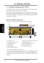
Страница 12: ...e with the following components III INSTALLATION CPU III INSTALLATION 1 Top support bar 1 7 ASUS C P2T CPU termination card 1 2 Pan head washer screws 6 8 Guide plate retainer 1 3 Pan head screws 2 9 Pan trim head washer screw 1 4 Plastic rings 2 10 Hex washer screws 2 5 Guide plate 1 11 Support bar brackets 2 6 Retention mechanisms 2 Common screws available with system case Two are provided to ac...

Страница 13: ...ge any static electricity that may have accumulated in your body NOTE The numbers in parentheses and in boldface in the following and succeed ing steps pertains to the item number as indicated in the component list on page 12 1 Install theTop Support Bar Place the top support bar 1 over the top edge of the CPU card Secure the bar in place starting at the middle with a pan head washer screw 2 and t...

Страница 14: ... the CPU will overheat Be sure that sufficient air circulation is available across the SEC cartridge s passive heatsink Without sufficient air circula tion the SEC cartridge could overheat and damage both the SEC cartridge and the baseboard You may install an auxiliary fan if necessary SEC Cartridge with Heatsink Side SEC Cartridge with Heatsink Top Push each end of the clamps until they lock The ...

Страница 15: ...nect the leads into the CPU card s fan connectors AAVID Heatsink The procedures for installing the AAVID heatsink with fan is similar as that for the heatsink without a fan You will not however be able to use the heatsink support top bar because of the fan The heatsink support top bar will however still be included in the package in case you use a heatsink without a fan Elan Vital Heatsink The pro...

Страница 16: ...ly until it is fully inserted 6 Secure the SEC Cartridge Secure the SEC cartridge in place by pushing the SEC cartridge locks outward so that the lock shows through the retention mechanism s lock holes 7 IMPORTANT If you are installing only one processor you may install it in either the right or left SEC slot You must terminate however the empty slot with the ASUS C P2T CPU termination card 7 to m...

Страница 17: ... 9 Set Jumpers Refer to CPU to BUS Frequency Ratio and BUS Frequency Selection baseboard s for the jumper settings NOTE If you are using a heatsink with fan and CPU fan connectors are not avail able on the baseboard you may now connect the CPU fan leads into their corre sponding connectors on the CPU card If your baseboard has CPU fan connectors connect the leads into the baseboard s connectors af...

Страница 18: ...ase The system case must be a full sized server case to allow a clear ance for the components installed on the CPU card The CPU card also requires that the floppy disk and CD ROM drives must not be placedoverthebaseboard Besure that the system cabinet has a mini mum clearance area of 13 5 x 9 25 x 5 34 3 x 23 5 x 12 7cm for all the components to fit as illus trated on the next page For a list of r...

Страница 19: ...nsion Cards ISA 3 Long Expansion Card ISA 2 Long Expansion Card ISA 1 PCI 5 MediaBus Long Card PCI 4 Long Expansion Card PCI 3 Short Expansion Card PCI 2 Short Expansion Card PCI 1 Long Expansion Card System Cabinet Clearance Area Requirement PS 2 Mouse PS 2 Keyboard The C PKND CPU card as assembled and installed on the baseboard ...

Страница 20: ... in case you need to cover the port again WARNING Beforehandlinganycomponents dischargestaticelectricityfromyour body by using a grounded wrist strap or by touching the unpainted metal part of the case or the power supply case While working inside the computer ground yourself frequentlytodischargeanystaticelectricitythatmayhaveaccumulatedinyourbody 5 Align the connector end of the CPU card with th...

Страница 21: ...the installation You may now proceed to the next step Power Connection Procedures 11 10 9 6 Secure the card by inserting and tightening the pan trim head washer screw 9 into the CPU card expansion port slot and the bottom retainer screw 10 into the system case Install the support bar bracket 11 appropriate to your system case if needed You may have to drill a hole to the system case to accommodate...

Страница 22: ... do not see anything within 30 seconds from the time you turn on the power the system may have failed a power on test Recheck your jumper settings and connections or call your retailer for assistance 7 During power on hold down Delete to enter BIOS setup Follow the instruc tions in section IV BIOS SOFTWARE Powering off yourcomputer You must first exit or shut down your operating system before swit...

Страница 23: ... ms2 hinet net Desktop Part Number T10 DK Server Part Number S50 Chenbro Micom Co Ltd Address 5F 11 Chung Shan Road Lane 327 Alley 11 Chung Ho City Taipei Hsien Taiwan ROC Telephone 886 2 248 9505 Fax 886 2 242 7304 Email serverdept chenbro com tw WWW www chenbro com tw Server Part Number 9611 Chieftec Industrial Co Ltd Address 6F 242 Chang De Road Sec 4 Taipei Taiwan ROC Telephone 886 2 883 2491 ...

Страница 24: ...the BIOS version check the last four numbers of the code displayed on the upper left corner of your screen during the test routines when you turn on your machine xxxxkm xxx BIOS file for the C PKND on the baseboard with LM78 available on Rev 2 04 or later baseboards xxxxk xxx BIOS file for the C PKND on the baseboard without LM78 Rev 1 41 or earlier baseboards Flash Memory Writer Utility The flash...

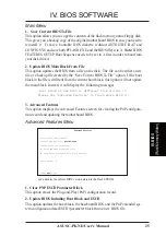
Страница 25: ... from the current boot block this option will not update the main block Instead it will display the following messages Boot Block of New BIOS is different from old one Please Use Advanced Features to flash whole BIOS 3 Advanced Features This option displays the Advanced Features screen for clearing the PnP configura tion record and updating the motherboard BIOS Advanced Features Menu 1 Clear PNP E...

Страница 26: ...the floppy disk you created earlier 4 At the DOS prompt type PFLASH Enter 5 Select option 2 Update BIOS Main Block From File from the Main Menu or option 2 Update BIOS Including Boot Block and ESCD from the Advanced Features menu if prompted by option 2 of the Main Menu 6 On the next screen displayed type the complete filename and extension of the new BIOS file and press Enter The utility then upd...

Страница 27: ...When you install the baseboard reconfigure your system or receive a Run Setup message you will need to enter new setup information This section describes how to configure your system using this utility The BIOS ROM of the system stores the Setup utility When you turn on the com puter the system provides you with an opportunity to start Setup During the Power On Self Test POST press Delete to run t...

Страница 28: ...ou change your system hardware configuration you will need to respecify the configuration values The configuration values usually get lost or corrupted when the power of the onboard CMOS battery weakens The preceding screen provides you with a list of options At the bottom of this screen are the control keys for this screen Take note of these keys and their respective uses User configurable fields...

Страница 29: ...nstall other vendor s SCSI controller card refer to their respective documentations on how to install the required SCSI drivers For IDE hard disk drive setup you can Use the Auto setting for detection during bootup Use the IDE HDD AUTO DETECTION in the main menu to automatically enter the drive specifications Enter the specifications manually by using the User option The entries for specifying the...

Страница 30: ...noted in parenthesis next to each function heading Drive A Drive B None These fields record the types of floppy disk drives installed in your system The available options for drives A and B are 360KB 5 25 in 1 2MB 5 25 in 720KB 3 5 in 1 44MB 3 5 in 2 88MB 3 5 in None To enter the configuration value for a particular drive highlight its corresponding field and then select the drive type using the l...

Страница 31: ...t to each function heading Details of BIOS Features Setup Virus Warning Disabled This field protects the boot sector and partition table of your hard disk against acci dental modifications Any attempt to write to them will cause the system to halt and display a warning message If this occurs you can either allow the operation to continue or use a bootable virus free floppy disk to reboot and inves...

Страница 32: ... looks first for an operating system Options are C A A CDROM C CDROM C A D A E A F A C only and A C The setup default setting is to check first the hard disk and then the floppy drive that is C A Boot Up Floppy Seek Disabled When enabled the BIOS will seek drive A once Floppy Disk Access Control R W This allows protection of files from the computer system to be copied to floppy disks by allowing t...

Страница 33: ...o RAM enhances system performance because information access is faster than the ROM C8000 CBFFF Shadow to DC000 DFFFF Shadow Disabled These fields are used for shadowing other expansion card ROMs If you install other expansion cards with ROMs on them you will need to know which addresses the ROMs use to shadow them specifically Shadowing a ROM reduces the memory available between 640K and 1024K by...

Страница 34: ...nly Leave on default setting of RAS Only because this is the current standard CPU to PCI IDE Posting Enabled Leave on default setting of Enabled so that the CPU to PCI IDE posting cycles are treated as normal I O write transactions USWC Write Posting Enabled Leave on default setting of Enabled to allow USWC write posting during I O bridge access CPU to PCI Write Post Enabled The default setting of...

Страница 35: ...expan sion cards that specifically require this setting This makes the memory from 15MB and up unavailable to the system Expansion cards can only access memory up to 16MB The default is Disabled DRAM and ECC If all your DRAM modules have parity chips e g 8 chips 4 parity chips they are considered 36bits This motherboard sums the memory per bank and therefore two modules will give 72bits and the fo...

Страница 36: ...ration at maximum speed ECP allows the parallel port to operate in bidirectional mode and at a speed faster than the maximum data transfer rate ECP EPP default allows normal speed operation in a two way mode ECP DMA Select 3 This selection is available only if you select either ECP or ECP EPP as the Parallel Port Mode Select either DMA Channel 1 3 default or Disable UART2 Use Infrared Disabled Whe...

Страница 37: ... Disable disables the power saving features User Define the default setting allows you to set power saving options according to your preference IMPORTANT Advanced Power Management APM should be installed to keep the system time updated when the computer enters suspend mode acti vated by the BIOS Power Management For DOS environments you need to add DEVICE C DOS POWER EXE in you CONFIG SYS For Wind...

Страница 38: ...Doze Mode Standby Mode and Suspend Mode The system automatically wakes up from any power saving mode when there is system activity such as when a key is pressed or when there is activity detected from the enabled IRQ channels HDD Power Down shuts down any IDE hard disk drives in the system after a pe riod of inactivity This time period is user configurable at 1 15 Min or Disable This feature does ...

Страница 39: ...ach field is Auto which uses auto routing to determine IRQ use The other options are manual settings of NA 5 7 9 10 11 12 14 or 15 for each slot PCI Latency Timer 32 PCI Clock The default setting of 32 PCI Clock enables maximum PCI performance for this motherboard IRQ xx Used By ISA No ICU These fields indicate whether or not the displayed IRQ for each field is being used by a legacy non PnP ISA c...

Страница 40: ...y its address range select a base address from the six available ranges The ISA MEM Block SIZE field will then be available for selecting the block size If you have more than one legacy ISA card in your system that requires to use this address range you can increase the block size to either 8K 16K 36K or 64K If you are using an ICU to accomplish this task leave ISA MEM Block BASE to its default se...

Страница 41: ...nd then Enter to abort This feature does not affect the fields on the Standard CMOS Setup screen Load Setup Defaults This Load Setup Defaults option allows you to load the default values to the sys tem configuration fields These default values are the optimized configuration set tings for the system To load these default values highlight Load Setup Defaults on the main screen and then press Enter ...

Страница 42: ...upply Fan Speed in Rotations Per Minute RPM These values refresh upon any key entry in the BIOS setup screens Set to Ignore if one of these are not used so that error messages will not be given Thermal Monitor MB Temperature xxxC xxxF The onboard hardware monitor can detect the baseboard temperatures These values refresh upon key entries Set to Ignore only if necessary Voltage Monitor VCORE 3 3V 5...

Страница 43: ...characters long type in your password and then press Enter The system confirms your password by asking you to type it again After setting a password the screen automatically re verts to the main screen NOTE The SMARTALARM LM78 SETUPis only avaiable on baseboards with the optional onboard LM78 chip To implement the password protection specify in the Security Option field of the BIOS Features Setup ...

Страница 44: ...can only install two IDE hard disk drives Your IDE controller must support the Enhanced IDE features to use Drive E and Drive F The onboard PCI IDE controller supports Enhanced IDE with two connectors for connecting up to four IDE devices If you want to use another controller that supports four drives you must disable the onboard IDE controller see Chipset Features Setup When autodetection is comp...

Страница 45: ...k do not accept them Press N to reject the presented settings and enter the correct ones manually from the Standard CMOS Setup screen Save Exit Setup Select this option to save into the CMOS memory all modifications you specified during the current session To save the configuration changes highlight the Save Exit Setup option on the main screen and then press Enter NOTE The SMARTALARM LM78 SETUPis...

Страница 46: ...user to update the whole BIOS This DMI Configura tion Utility also allows the system integrator or end user to add additional informa tion into the MIFD such as serial numbers housing configurations and vendor information Information not detected by the baseboard BIOS has to be manually entered through the DMI Configuration Utility and updated into the MIFD This DMI Configuration Utility provides ...

Страница 47: ...iting The orange text shows autodetected information and are not available for editing Selecting Press ENTER for detail in blue displays a second pop up menu Use the Plus Sign or Minus Sign keys to change the set tings Press Enter to exit and save or press ESC to exit and not save If you made changes pressing ESC prompts you to answer Y or N Enter Y to go back to the left screen and save enter N t...

Страница 48: ...ess ESC and a message Bad File Name is displayed to show it was not saved Load MIFD You can load the disk file to memory by entering the drive and path and filename Load BIOS Defaults You can load the BIOS defaults from a MIFD file and can clear all user modified and added data You must restart your computer for the defaults to be saved back into the Flash BIOS V DMI Using DMI Utility ...

Отзывы: