


User’s Manual
A-7
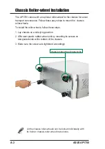
6. Remove the six (6)
power case top screws.
5. Remove the four (4) power
case side screws.
Make sure the power case is well supported or held when
releasing the power case screws. The power case may
accidentally detach and cause damage to the other
components of the server system.
7. Slowly pull-out the power case.
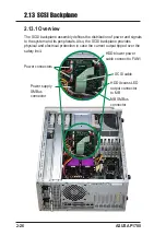
Power case rear view
Power case top view
Power case cable connectors
1
2
4
3
5
6
7
9
8
1. 24-pin ATX power
2. 8-pin AUX 12V power
3. Spare
4. SCSI backplane
5. SCSI backplane
6. Spare
7. CD-ROM
8. Floppy drive
9. SMBUS cable for
power supply
Содержание AP1700
Страница 1: ...Intel Xeon Tower 5U Rackmount Server AP1700 User s Manual with 533MHz FSB support ...
Страница 8: ...viii ASUS AP1700 ...
Страница 46: ...2 28 ASUS AP1700 ...
Страница 54: ...A 8 ASUS AP1700 ...
Страница 58: ...A 12 ASUS AP1700 ...


