background image


© ASTRALPOOL 2008. ALL RIGHTS RESERVED. CONFIDENTIAL AND PROPRIETARY DOCUMENT.


Page 29 of 69 


ESPAÑOL

10  AVERIAS: SUS CAUSAS Y SOLUCIONES. 

Las circunstancias por las que su unidad deshumidificadora podría no funcionar se detallan a 
continuación: 

¾


El equipo no se pone en marcha:  


Interruptor de maniobra abierto:

 Comprobar que no hay ningún cortocircuito en el cuadro de 

maniobra, reparar el posible cortocircuito. 


La bobina del contactor no se activa:

 Comprobar que no está quemada en cuyo caso sustituir. 

Comprobar los enclavamientos que activan dicha bobina. 


Térmico abierto

: Comprobar el voltaje de la línea. Comprobar que las condiciones de trabajo 

son las correctas. Excesivo consumo del compresor. Cortocircuito en la línea del compresor. 


Presostato de baja abierto:

 Comprobar el funcionamiento de este, sustituyéndolo si fuera 

necesario. Comprobar el correcto funcionamiento del ventilador. Comprobar la carga de gas 
del equipo (perdida de refrigerante, equipo con fugas) para solucionar esto ver apartado carga 
de gas. 


Comprobar que hay buena circulación de aire en la batería de intercambio:

 Comprobar que no 

hay obstrucciones en el circuito frigorífico eliminándola si ocurriera esto. Comprobar el correcto 
funcionamiento de la válvula Termostática, comprobando que el bulbo no ha perdido gas y que 
la toma de presión no está obstruida, sustituir en caso necesario. 


Presostato de alta abierto:

 Comprobar el funcionamiento de este, sustituyéndolo si fuera 

necesario. Comprobar la carga de gas del equipo (exceso de refrigerante) para solucionar esto 
ver apartado carga de gas. Comprobar que no hay obstrucciones en el circuito frigorífico 
eliminándola si ocurriera esto. 


Ciclo de desescarche

: Las condiciones de aire ambiente no son adecuadas (temperaturas 

demasiado bajas). La máquina no opera en estas condiciones, en este caso se recomienda 
desconectar la máquina. 

¾


Nivel de aceite bajo: 


Carga inicial de aceite baja

: Completar hasta el nivel necesario. 


Manchas de aceite en el equipo:

 Comprobar fugas en el circuito frigorífico reparándolas, 

verificar que las válvulas de alta y baja están bien apretadas, en caso de avería sustituirlas. 


¾


El equipo funciona en ciclos demasiado cortos


Presostato de baja se abre y se vuelve a cerrar:

 Verificar los apartados del punto anterior 

“presostato de baja abierto”. 


Contacto intermitente en el control de la máquina

: Reparar o reemplazar el fallo del control 

eléctrico. Comprobar la sonda de temperatura. 


Comprobar que el equipo no es demasiado grande para la instalación. 


Содержание ASTRAL CDP-2

Страница 1: ...ERIE ASTRAL CDP LINE ASTRAL CDP LINE DESHUMIDIFICADOR SERIES ASTRAL CDP LINE ASTRAL CDP LINE DEHUMIDIFIER S RIES ASTRAL CDP LINE ASTRAL CDP LINE DEHUMIDIFIER ASTRAL CDP LINE SERIES TECHNICAL MANUAL ST...

Страница 2: ...ASTRALPOOL 2008 ALL RIGHTS RESERVED CONFIDENTIAL AND PROPRIETARY DOCUMENT Page 2 of 69 FGHFGDH FGHFGH PUETA EN MARCH A Y FUNCIONAMIENTO...

Страница 3: ...STRAL CDP LINE SERIE ASTRAL CDP LINE DEUMIDIFICATORE SERIE ASTRAL CDP LINE ASTRAL CDP LINE DESHUMIDIFICADOR SERIES ASTRAL CDP LINE ASTRAL CDP LINE DEHUMIDIFIER S RIES ASTRAL CDP LINE TECHNICAL MANUAL...

Страница 4: ...DE LA CARCASA 26 9 CARGA DE GAS REFRIGERANTE 27 10 AVERIAS SUS CAUSAS Y SOLUCIONES 29 11 RECICLAJE DEL PRODUCTO 31 12 REPUESTOS 32 12 1 VISTA AMPLIADA CDP LINE 34 13 MODELOS 35 14 GARANT AS 35 FIGURAS...

Страница 5: ...RUCTIONS 55 8 1 HOUSING REMOVAL 56 9 REFRIGERANT CHARGE 57 10 TROUBLESHOOTING GUIDE 59 11 PRODUCT RECYCLING 61 12 REPLACEMENT PARTS 62 12 1 CDP LINE EXPLODED VIEW 64 13 MODELS 65 14 GUARANTEES 66 FIGU...

Страница 6: ...r el buen funcionamiento de la unidad deshumidificadora es necesario realizar un mantenimiento peri dico realizar un buen uso de ella y de no sobrepasar los l mites marcados por el fabricante 4 La ins...

Страница 7: ...forma definitiva la climatizaci n de su piscina Le rogamos dedique unos minutos a la lectura de este manual para que pueda conocer el potencial de la m quina y tener en cuenta todas las circunstancia...

Страница 8: ...dora se utiliza en instalaciones donde se requiere un control de humedad y temperatura individual de la zona aprovechando el calor latente de vaporizaci n y el propio rendimiento del equipo en calenta...

Страница 9: ...rico con control total para garantizar un rendimiento ptimo con un m nimo consumo de energ a en todo momento La aplicaci n se basa en el control de una serie de elementos para mantener unas condicione...

Страница 10: ...ia Nominal cv 1 1 1 4 1 3 4 2 Tipo Centr fugo Centr fugo Centr fugo Centr fugo Unidades 1 1 1 1 Caudal m3 h 700 800 1 000 1 200 Consumo Amp 1 1 1 1 1 1 1 1 Voltaje V 220 220 220 220 Gas Refrigerante R...

Страница 11: ...liente las conexiones para el circuito hidr ulico presentan una distancia de 58 mm entre si y una altura respecto a a la base de la m quina de 610 mm 25mm 25mm Dos conexiones para el circuito hidr uli...

Страница 12: ...os Consulte a su instalador Si se produce alguna anomal a olor a quemado etc pare la unidad retire la toma o corte la alimentaci n La reparaci n o instalaci n no deben ser realizadas por el cliente El...

Страница 13: ...ponga nada Podr a producirse un accidente por la caida del objeto o de la unidad Verifique la compatibilidad de red con los datos indicados en el aparato antes de comenzar la instalaci n de la unidad...

Страница 14: ...a tensi n ITC BT 31 Las conexiones el ctricas e hidr ulicas deben efectuarse seg n la normas en vigor NF C 15 100 CE 1 364 Las canalizaciones de las conexiones deben ser fijas Durante el funcionamient...

Страница 15: ...ecesidades y condiciones de instalaci n Se instalan cables cuya secci n cumpla con las normativas actuales e impidan un calentamiento de estos y una ca da de tensi n A titulo orientativo se puede usar...

Страница 16: ...onectar los cables de entrada de corriente a la borna de entrada de la m quina 6 Conectar el cable de toma tierra en la borna correspondiente para ello Se debe cumplir en todo momento lo que deja refl...

Страница 17: ...ASTRALPOOL 2008 ALL RIGHTS RESERVED CONFIDENTIAL AND PROPRIETARY DOCUMENT Page 17 of 69 ESPA OL Figura 3 Conexionado del compresor EQUIPO CON RESISTENCIAS ELECTRICAS...

Страница 18: ...ASTRALPOOL 2008 ALL RIGHTS RESERVED CONFIDENTIAL AND PROPRIETARY DOCUMENT Page 18 of 69 ESPA OL Figura 4 Esquema el ctrico equipos con resistencias el ctricas EQUIPO CON BATERIA DE AGUA CALIENTE...

Страница 19: ...ASTRALPOOL 2008 ALL RIGHTS RESERVED CONFIDENTIAL AND PROPRIETARY DOCUMENT Page 19 of 69 ESPA OL Figura 5 Esquema el ctrico equipos con bater a de agua caliente Bomba de recirculaci n no incluida...

Страница 20: ...componentes internos del mismo Por esta raz n se ha incorporado un termostato de bulbo cuya misi n es tomar medidas de la temperatura del aire ambiente de modo que si esta temperatura disminuye por d...

Страница 21: ...roduzcan fisuras o roturas en la instalaci n hidr ulica En la conexi n del equipo a la red hidr ulica no deberemos forzar los tubos de Cobre De esta forma evitaremos la rotura de los mismos Se ha de t...

Страница 22: ...01 7005 es una combinaci n de higrostato y regulador de temperatura adecuado para ser empleado en peque as piscinas ba eras vestuarios salas de ba o Es necesario cuidar que el aparato no quede expuest...

Страница 23: ...idad absorbida Dar tensi n al equipo conectando el interruptor general de fuerza externo a la unidad Una vez conectada la m quina verificar la intensidad absorbida por la fase Con el equipo en marcha...

Страница 24: ...1 VENTILADOR SIEMPRE EN MARCHA recomendado En este modo de funcionamiento el ventilador permanecer en marcha siempre que la m quina est conectada aunque el recinto a climatizar se encuentre dentro de...

Страница 25: ...iadamente a trav s de la misma Para efectuar su limpieza utilice agua con poca presi n y detergentes no abrasivos o espec ficos para ello COMPRESOR Se debe de comprobar el aceite del compresor en los...

Страница 26: ...var siguiendo los siguientes pasos Partiendo de la posici n inicial de la unidad pasaremos a retirar los dos tornillos laterales 1 2 que sujetan la carcasa exterior Seguidamente procederemos a inclina...

Страница 27: ...e introducirlo en el circuito de baja presi n a trav s de un cargador sistema de expansi n Despu s de haber puesto el circuito frigor fico bajo vac o despu s de haber instalado el cargador y haber con...

Страница 28: ...ferentes instrumentos de b squeda de fugas aunque no todos son suficientemente sensibles para ciertos refrigerantes Es muy importante seleccionar un detector adecuado para el refrigerante que incorpor...

Страница 29: ...o elimin ndola si ocurriera esto Comprobar el correcto funcionamiento de la v lvula Termost tica comprobando que el bulbo no ha perdido gas y que la toma de presi n no est obstruida sustituir en caso...

Страница 30: ...de l quido revisando el recalentamiento ver apartado carga de gas INDICACIONES GENERALES Cualquier intervenci n en el circuito frigor fico debe realizarse siguiendo las normas de seguridad en vigor re...

Страница 31: ...pueda contener PVC El plastificante m s usado en las aplicaciones de PVC es el DEHP dietil hexil ftalato Los ensayos realizados en diversos laboratorios demuestran que no presenta riesgo alguno para l...

Страница 32: ...SISTENCIAS CDP 4 5 41501R0004 11 CHAPA SOPORTE CLIXON TODOS 41493R0011 12 MORDAZA TAPA TRASERA BATERIA EVAPORADORA TODOS 41493R0012 13 TAPA SUPERIOR CUADRO ELECTRICO CDP 2 3 41493R0013 13 TAPA SUPERIO...

Страница 33: ...RIA EVAPORADORA CDP 2 3 41493R0039 38 TAPA TRASERA BATERIA EVAPORADORA CDP 4 5 41501R0020 39 CARCASA EXTERIOR CDP 2 3 41493R0040 39 CARCASA EXTERIOR CDP 4 5 41501R0021 40 CHAPA CUADRO ELECTRICO CDP 2...

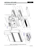
Страница 34: ...ASTRALPOOL 2008 ALL RIGHTS RESERVED CONFIDENTIAL AND PROPRIETARY DOCUMENT Page 34 of 69 ESPA OL 12 1 VISTA AMPLIADA CDP LINE Figura 13 Vista ampliada de la unidad deshumidificadora...

Страница 35: ...MPOTRADO 41503 ESTANDAR 41504 CDP LINE 4 BAT AGUA 12 KW EMPOTRADO 41505 ESTANDAR 41506 BAT ELECT 5 KW EMPOTRADO 41507 ESTANDAR 41508 CDP LINE 5 BAT AGUA 12 KW EMPOTRADO Tabla 5 Lista de modelos dispon...

Страница 36: ...s productos a que hace referencia este manual 2 3 Para la eficacia de esta garant a el comprador deber seguir estrictamente las indicaciones del fabricante incluidas en la documentaci n que acompa a a...

Страница 37: ...e of the unit and not to exceed the limits set by the manufacturer 4 The installation must be made by qualified technical personnel These personnel commit themselves to observe the instructions of the...

Страница 38: ...ier unit into the equipment that can solve once and for all the air conditioning of your swimming pool Please read this manual carefully It will help you to learn the full potential of the equipment a...

Страница 39: ...unit for swimming pools is used in facilities requiring individualised humidity control and temperature management taking advantage of the existing heat vapours and the equipment s heat output in ord...

Страница 40: ...andard or built in Electric Panel Electrical control panel for complete process control and to guarantee optimum performance with minimum power consumption at all times The process control is based on...

Страница 41: ...Nominal Power cv 1 1 1 4 1 3 4 2 Type Centrifugal Centrifugal Centrifugal Centrifugal Units 1 1 1 1 Flow m3 h 700 800 1 000 1 200 Consumption Amp 1 1 1 1 1 1 1 1 Voltage V 220 220 220 220 Refrigerant...

Страница 42: ...istance between external connections for the hydraulic connections is 58 mm and a distance to the base of the equipment of 610 mm 25mm 25mm Two connections for the hydraulic circuit in case of machine...

Страница 43: ...ce burning smell etc stop the unit retrieve the plug or turn the power off The repair or installation should never be performed by the client The unit must never be put under water or mud discharges a...

Страница 44: ...ident Do not mount or place anything upon the unit The fall of the object or the unit could cause an accident Verify the network compatibility with the data specified in the unit before starting to in...

Страница 45: ...ary Technical Instructions Low Voltage 31 ITC BT 31 The electrical and hydraulic connections must be made according to the applicable regulations NF C 15 100 EC 1 364 The ducting for the connections m...

Страница 46: ...tion needs and conditions All wiring should comply with local and national electric codes and should not be prone to overheating and subsequent voltage failures As a guide you can use the general powe...

Страница 47: ...power supply is turned off 5 Connect the power supply wires to the unit s input terminal 6 Connect the grounding wire to its corresponding terminal All local and national electricity codes concerning...

Страница 48: ...ASTRALPOOL 2008 ALL RIGHTS RESERVED CONFIDENTIAL AND PROPRIETARY DOCUMENT Page 48 of 69 ENGLISH ELECTRICAL BATTERY EQUIPPED Figure 4 Electrical Scheme for electrical battery equipped models...

Страница 49: ...OOL 2008 ALL RIGHTS RESERVED CONFIDENTIAL AND PROPRIETARY DOCUMENT Page 49 of 69 ENGLISH HEATING BATTERY EQUIPPED Figure 5 Electrical Scheme for heating battery equipped models Recirculation pump not...

Страница 50: ...age to the internal components of the equipment For this reason a thermostat with probe has been included whose mission is to take ambient air temperature so if temperature drops below 21 C the thermo...

Страница 51: ...der to avoid vibrations which may cause cracks or breakage in the hydraulic connections In order to avoid possible breakage do not force the copper tubes connected to the water supply Take into accoun...

Страница 52: ...e of obstruction Obstacles should be maintained at a distance 5 CONTROLLER The HYG E 7001 7005 is a combination of a hygrostat and a room temperatura controller for use in swimming pools bathtubs dres...

Страница 53: ...intensity absorbed Give power to the equipment by connecting the general power switch on the outside of the unit Once the unit is connected verify the intensity absorbed With the machine running verif...

Страница 54: ...ting modes user selectable OPERATING MODE 1 FAN ALWAYS ON recommended In this operating mode the fan will always be on if the equipment main switch is ON even if the enclosure to be regulated is withi...

Страница 55: ...them In order to clean it use water little pressure and non abrasive detergents or cleaning liquids made specifically for it COMPRESSOR Compressor oil must be checked in those unit models provided wi...

Страница 56: ...ious maintenance procedures is to be carried following these steps Starting on the initial position of the unit proceed to remove the two side screws 1 2 that attach the housing Then proceed to tilt t...

Страница 57: ...frigerant bottle must be introduced in the low pressure circuit by means of a charger expansion system After having discharged the cooling circuit and after having installed the charger and connected...

Страница 58: ...re are various tools on the market used in order to detect leaks although not all of them are sufficiently sensitive to certain types of refrigerants It is very important to choose an adequate detecto...

Страница 59: ...the obstruction if necessary Verify that the thermostatic valve is operating properly checking the bulb has no gas leaks and that the pressure inlet is free of obstruction Replace if needed High pres...

Страница 60: ...that the noise does not come from any fluid leak from overheating see section of refrigerant charge GENERAL INSTRUCTIONS Any intervention in the refrigeration circuit must be made following the appli...

Страница 61: ...lection from the rest of urban rubbish Possible effects over the environment or human health of the dangerous materials it may contain PVC The most used plastifying agent in the different PVC applicat...

Страница 62: ...5 41501R0004 11 CLIXON PLATE ALL 41493R0011 12 REAR PLATE ROD ALL 41493R0012 13 UPPER ELECTRICAL PLATE CDP 2 3 41493R0013 13 UPPER ELECTRICAL PLATE CDP 4 5 41501R0005 14 AIR INLET OUTLET ROUND CDP 2 3...

Страница 63: ...FRONT PLATE CDP 4 5 41501R0020 39 EXTERIOR ENCLOSURE CDP 2 3 41493R0040 39 EXTERIOR ENCLOSURE CDP 4 5 41501R0021 40 ELECTIRCAL PLATE CDP 2 3 41493R0041 40 ELECTIRCAL PLATE CDP 4 5 41501R0022 41 GROUND...

Страница 64: ...ASTRALPOOL 2008 ALL RIGHTS RESERVED CONFIDENTIAL AND PROPRIETARY DOCUMENT Page 64 of 69 ENGLISH 12 1 CDP LINE EXPLODED VIEW Figure 13 CDP LINE exploded view...

Страница 65: ...LINE 2 HEAT BATTERY 6 KW BUILT IN 41497 STANDARD 41498 ELECT BATTERY 4 KW BUILT IN 41499 STANDARD 41500 CDP LINE 3 HEAT BATTERY 9 KW BUILT IN 41501 STANDARD 41502 ELECT BATTERY 5 KW BUILT IN 41503 ST...

Страница 66: ...re in the installation procedure which is related to the lack of observance of the instructions contained in this manual will mean the cancellation of the warranty IMPORTANT The warranty will only hav...

Страница 67: ...1 This warranty covers the products referred to in this manual 2 3 For the effectiveness of this warranty the buyer will have to strictly follow the manufacturer instructions included in the documenta...

Страница 68: ...atibility directive 2004 108 EC and its modifications Low voltage equipment directive 2006 95 EC Directive 2000 14 CE concerning noise produced by equipment for outdoors use as amended by Directive 20...

Страница 69: ...CONTENU DE CE DOCUMENT SANS AVIS DE WIR BEHALTEN UNS DAS RECHT VOR DIE CHARAKTERISTIKA UNSERER PRODUKTE ODER DEN INHALT DIESES DOKUMENTS OHNE VORHERIGE ANK NDIGUNG VOLLST NDIG ODER TEILWEISE ZU NDERN...

Отзывы: