Pitch Pipe Back
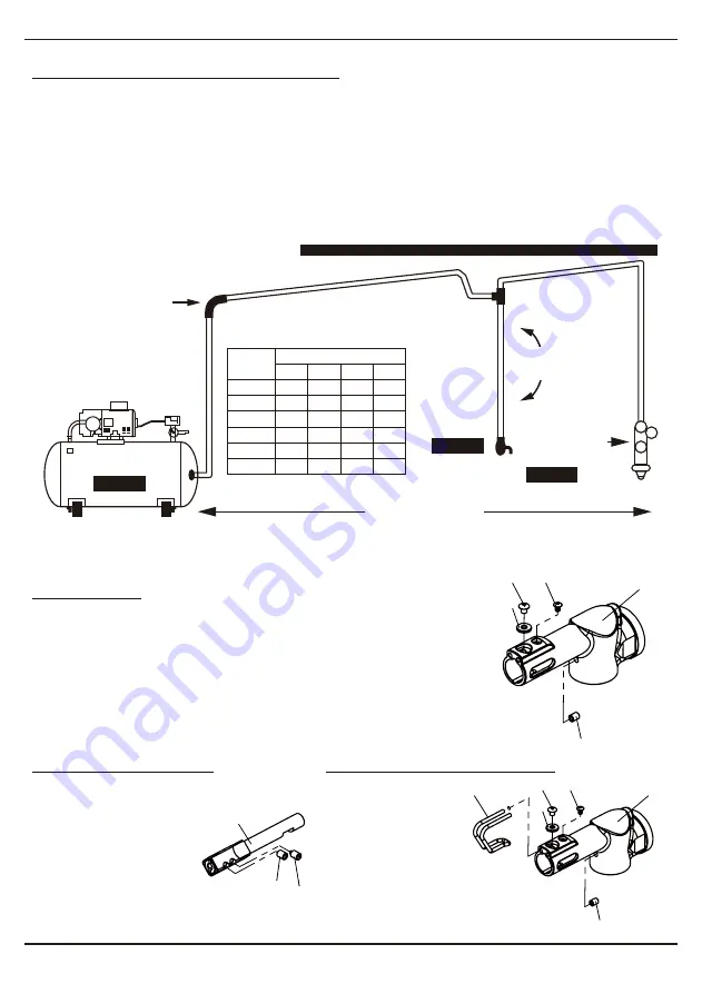
Toward Air Receiver
Oil and Water Extractor should be at least 25 ft. from the compressor.
Further if possible.
Oil and Water
Extractor
PIPE SIZE, I.D. (Inches)
OPERATION
To properly maintain tool, grease can be applied as needed. To grease
tool remove tap screw (#26) with hex wrench supplied. Force grease
into location using grease kit. Always turn off the air supply, drain hose
of air pressure and detach tool from air supply before installing,
removing or adjusting any part or accessory on this tool, or before
performing any maintenance on this tool.
NOTE: During operation, safety goggles should always be worn to
guard against flying rust and chips(users & bystanders).
TO CHANGE BLADES
1. Detach tool from air supply.
2. Use (#51) hex wrench
provided to loosen (#26 &
#33) set screws.
3. Insert blade into
blade guide (#29) and
retighten (#26!)
set screws.
TO ADJUST BLADE GUARD
1. Detach tool
from air supply.
2. Use (#51) 3mm
hex wrench
provided to loosen
(#46) set screw.
3. Adjust (#30) saw blade guard
to desired position and
retighten (#46) set screw.
04
Gear Driven Heavy Duty Air Saw
936
SUGGESTED AIR LINE CONNECTION
The oil and water extractor should not be mounted on or near the air compressor.
The temperature of air is greatly increased during compression. As the air cools down to room
temperature, in the air line, on its way to the Air Power Tool, the moisture contained in it condenses.
Thus, for maximum effectiveness, the oil and water extractor should be mounted at some point in the
air supply system where the temperature of the compressed air in the line is likely to be lowest.
Air lines must be properly drained daily. Each low point in an air line acts as a water trap. Such points
should be fitted with an easily accessible drain. See diagram below. Pitch all air lines back towards the
compressor so that condensed moisture will flow back into the air receiver where it can be drained off.
Drain daily.
Install Drain
at Each Low Point
COMPRESSOR UNIT
Drain Daily
Drain Daily
Drain Daily
25 FEET OR MORE
Air Flow
(CFM)
10
20
30
40
50
70
50
1/2"
3/4"
3/4"
1"
1"
1"
100
3/4"
3/4"
3/4"
1"
1"
1"
150
3/4"
3/4"
1"
1"
1"
1-1/4"
200
3/4"
1"
1"
1"
1-1/4"
Length of Pipe (feet)
26 33
29
45
48
46
27
26
30
45
48
46
27
26


