background image


Aston

®

 Tire Changer ATC-5733 User’s Manual


21 

www.astontechusa.com 


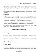
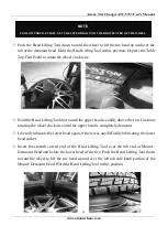
Push the Bead Lifting Tool down toward the wheel to lift the tire bead up and over the 
tab of the demount head. Hold the Bead Lifting Tool in this position.


Depress the Table 

Top Foot Pedal to rotate the wheel clockwise.   


Hold the Bead Lifting Tool down until the upper bead is solidly above the rim. Continue 
rotating the wheel clockwise until the upper bead is completely demount. 


Liberally lubricate the lower bead again, if there was any difficulty lubricating the lower 
bead earlier.   


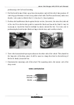
Insert  the  smooth  curved  end  of  the  Bead  Lifting Tool  over  the  tab  end  of  Mount  / 
Demount Head and below the lower bead of the tire. Push the Bead Lifting Tool down 
toward the wheel to lift the tire bead up and over the left tab side knob portion of the 
Mount/ Demount Head. Hold the Bead Lifting Tool in this position. 


NOTE:


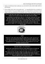
FOR LOW PROFILE TIRES, GET THE UPPER BEAD INTO THE DROP CENTER OF THE WHEEL. 


Содержание ATC-5733

Страница 1: ...Aston Tire Changer ATC 5733 User s Manual 1 www astontechusa com Installation Operation and Maintenance User s Manual Aston Tire Changer Model ATC 5733 ASTON TECHNOLOGIES INC...

Страница 2: ...safety instructions Keep them readily available for machine operators Make certain all operators are properly trained know how to safely and correctly operate the unit and are properly supervised All...

Страница 3: ...use if any component is broken or damaged Replace or repair damaged or worn parts immediately Never remove safety related components or device from the machine Do not use if safety related components...

Страница 4: ...d with a self gripping chuck and remote inflation gauge and valve Always inflate the tire to manufacturer s recommended cold operating pressure DO NOT OVER INFLATE Tire or wheel failure during and aft...

Страница 5: ...Aston Tire Changer ATC 5733 User s Manual 5 www astontechusa com Semi automatic swing arm tire changer Parameters rim 12 24 Tire width 14 28 tire diameter 1190mm TABLE OF CONTENTS...

Страница 6: ...roduction 10 2 2 Specifications 10 2 3 Transportation 11 2 4 Figure and part name 11 Installation and commissioning instructions 14 3 1 Installation Preparation 14 3 2 Precautions during installation...

Страница 7: ...Aston Tire Changer ATC 5733 User s Manual 7 www astontechusa com 6 1 Maintenance 32 6 2 Storage and scrap 35 Fault causes and Solutions 36 Parts List and Exploded Drawings 38 Warranty 40...

Страница 8: ...raining personnel 1 3 3 Tire disassemble is forbidden to use in explosive gas 1 3 4 Before the machine is connected the user must ensure that the use of power and gas supply and mechanical requirement...

Страница 9: ...il mist using models for ISO Hg and viscosity for ISO vg32 oil mist special oil such as Esso Fedis k32 1405 Mobil Vacouline KLUBER32 1 3 12 if the product is not used for a long time please A disconne...

Страница 10: ...quick disassemble and installation of wheel size of 10 to 28 the tire width of 110 380mm and the diameter of the tire is 1040mm 2 2 Specifications Special points Technical parameters Outer rim 12 24 I...

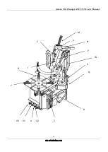
Страница 11: ...e lifting device such as a forklift or pallet jack Only personnel who are experienced and qualified on material handling procedures should handle any transportation or moving of machine 2 4 Figure and...

Страница 12: ...ger ATC 5733 User s Manual 12 www astontechusa com Y Turntable N Hypsokinesis arm K Locking Handle Q Oil Drier V1 Wheel Clamp Pedal C Inflatable E Hand Wheel M Vertical Reverse Spring W Three position...

Страница 13: ...Aston Tire Changer ATC 5733 User s Manual 13 www astontechusa com E K C P N I G Y R Z U V2 V1 Q M W V3...

Страница 14: ...ould be well lit easy to clean and should be away from oil grease brake lathe chips etc Avoid areas where bystanders and customers may be present Equipment installation location should be at least up...

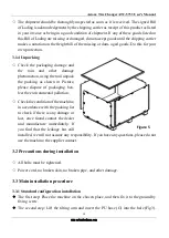
Страница 15: ...unpack the packing as shown in Picture please dispose of packaging box lest the environmental pollution Check the condition of the machine in accordance with the packing list to check if there is any...

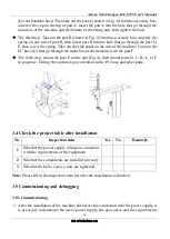
Страница 16: ...G that go through the main box of the machine with the part F The forth step mount the part E on the arm Fig 4 then mount parts D C B A G F in sequence During the operation pay attention to the PU hos...

Страница 17: ...ation direction the position of the two lines in the three phase plug should exchange position The second step depress the Bead Breaker Pedal start the Bead Breaker device when the pedal is released t...

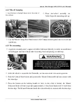
Страница 18: ...ext to but not on the rim or the sidewall of the tire Press the breaker pedal to actuate the blade and loosen the bead It may be necessary to loosen the bead in multiple locations around the tire Use...

Страница 19: ...pper and lower beads after loosening bead and placing on table top After the wheel is secured to the Turntable set the vertical shaft in the working position Push the Vertical Shaft down and position...

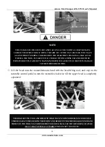
Страница 20: ...THE ARM OUT OF THE WAY AND BACK INTO PLACE AGAIN WITHOUT NEEDING TO REPOSITION THE HEAD WHEN CHANGING A LIKE SET OF WHEELS THE TOOL CLEARANCE MAY CHANGE WITH MACHINE USE AND SHOULD BE INSPECTED OFTEN...

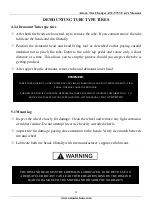
Страница 21: ...rotating the wheel clockwise until the upper bead is completely demount Liberally lubricate the lower bead again if there was any difficulty lubricating the lower bead earlier Insert the smooth curve...

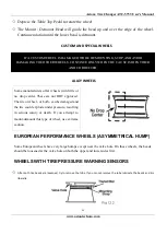
Страница 22: ...he valve hole on both the upper and lower sides first WHEELS WITH TIRE PRESSURE WARNING SENSORS After both tire beads are loosened try to remove the tube If you cannot remove the tube lubricate the be...

Страница 23: ...Inspect the wheel closely for damage Clean the wheel and remove any light corrosion or rubber residue Do not attempt to service heavily corroded wheels Inspect tire for damage paying close attention t...

Страница 24: ...R APPROVED RIM WIDTHS FOR TIRE SIZES ATTEMPTS TO FORCE A BEAD SEAT ON MISMATCHED TIRES AND WHEELS CAN CAUSE THE TIRE TO VIOLENTLY EXPLODE LEADING TO SERIOUS PERSONAL INJURY OR DEATH TO OPERATOR AND OR...

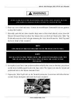
Страница 25: ...Assist Tower into position and lower the Roller Arms so that they press down on the tire to hold the upper bead in the drop center The Upper Arm must be locked and positioned next to the Mount demount...

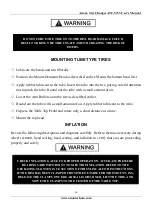
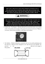
Страница 26: ...ate only a short distance at a time Mount the top bead INFLATION Review the following descriptions and diagrams carefully Refer to them as necessary during wheel restraint bead sealing bead seating an...

Страница 27: ...ve and into the tire for inflation Tire pressure is not indicated on the gauge in this position THE CLIP ON AIR CHUCK ON THE END OF THE INFLATION HOSE AND ALL INFLATION RELATED COMPONENTS SHOULD BE CH...

Страница 28: ...IONS PROVIDED IN THIS MANUAL FOR SAFE AND PROPER OPERATION DO NOT TAMPER WITH OR ATTEMPT TO ADJUST THE PRESSURE LIMITER TIRES REQUIRING INFLATION BEYOND 60 PSI SHOULD ONLY BE INFLATED IN A SAFETY CAGE...

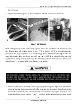
Страница 29: ...ult to bead seat Also note that asymmetrical hump and run flat tires are extremely difficult to bead seat Follow tire manufacturer s recommended procedure for bead seating Once tire pressure is indica...

Страница 30: ...S AT ALL PRESSURE LEVELS WHEN INFLATING THROUGH THE VALVE STEM KEEP HANDS ARMS AND ENTIRE BODYAWAY FROM INFLATING TIRE AN EXPLODING TIRE WHEEL OR BEAD SEALING EQUIPMENT MAY PROPEL UPWARD AND OUTWARD W...

Страница 31: ...LEVELS WHEN INFLATING THROUGH THE VALVE STEM KEEP HANDS ARMS AND ENTIRE BODYAWAY FROM INFLATING TIRE AN EXPLODING TIRE WHEEL OR BEAD SEALING EQUIPMENT MAY PROPEL UPWARD AND OUTWARD WITH SUFFICIENT FOR...

Страница 32: ...ge caused by the parts of other manufacturer and the damage caused by the disassembling of the safety device 6 1 2 Tending Regular use of diesel oil to clean the turntable to prevent the formation of...

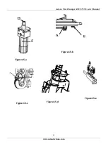
Страница 33: ...own in figure 15 e when cleaning or replacing silencer which controls the opening or closure of the clamps G follow the following steps first unscrew the 4 screws on the side of the box remove the lef...

Страница 34: ...Aston Tire Changer ATC 5733 User s Manual 34 www astontechusa com Figure 15 b Figure 15 a Figure 15 c Figure 15 d Figure 15 e...

Страница 35: ...f you want a long time storage of machine please disconnect all the energy supply and lubricate the skidway of the clamps on the turntable to prevent oxidation 6 2 2 Scrap In accordance with the law o...

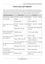
Страница 36: ...lace triangle belt Universal steering switch damage Replace universal steering switch Motor fault or line fault Check motor and external plug or socket Rotary clamp opening closing speed is slow Muffl...

Страница 37: ...Aston Tire Changer ATC 5733 User s Manual 37 www astontechusa com Cylinder sealing ring damage of pressure device Replace sealing ring...

Страница 38: ...Aston Tire Changer ATC 5733 User s Manual 38 www astontechusa com Parts List and Exploded Drawings...

Страница 39: ...Unit 8 5755000 Tilt Tower Plate Weld 9 57513200 Tower Weldment 10 575132310 Horizon Arm Unit 11 1011000 Tilt Back Cylinder unit 12 5754400 Bead Breaker Unit 13 301200 FRL Unit 14 8807000 Gear Box Unit...

Страница 40: ...e warranties do not extend to defects caused by ordinary wear abuse misuse shipping damage improper installation or lack of required maintenance This warranty is exclusive and in lieu of all other war...

Отзывы: