C
H A P T E R
1
M
A C H I N E
D
E S C R I P T I O N
2 6
6 7 1 0 D G
R I N D E R
O
P E R A T O R
S
A F E T Y
M
A N U A L
1 0 9 4 0 1 B
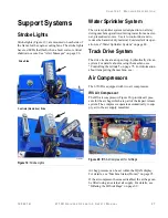
Operating with the Anvil Float Latch Plate
The optional “float” latch plate (Figure 17) allows free
movement of the anvil
.
The result is a less consistent
material size. This option is typically used when the
feed material contains many large solid objects or
ungrindable objects.
Figure 17:
Latching Assembly with Optional Float Type Anvil
Latch Plate
1
CAUTION
Serious damage possible.
If you operate with the IRS OFF, the machine has
no shutdown protection against damage due to
non-crushables in the feed.
If you hear or notice non-crushables in the
machine, shut down and inspect for damage.
A drawback is that less force will be required to lift the
anvil enough to trip the IRS limit switch and cause a
feed system slowdown. To avoid frequent work slow-
downs, the IRS limit switch is often placed into the dis-
abled mode when using the float latch plate. See “IRS
Limit Switch” on page 23.
Several possible grate configurations can be used with
the optional float latch plate, including having all four
grates in place.
Avoid using grates with openings larger than 6 inches
(15 cm) in the third and fourth grate positions. This is to
protect the conveyor belt from receiving direct blows
from large objects that may damage the belt or the
con-
veyor pan below it.
Material Discharge
System
After the material passes through the grates, it falls onto
the discharge conveyor, which, if equipped with a mag-
netic pulley, removes scrap metal before unloading the
material in a pile.
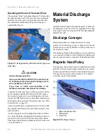
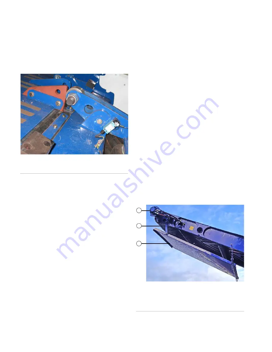
Discharge Conveyor
Reduced materials are transported away from the
grinder by the discharge conveyor (Figure 18). The dis-
charge conveyor uses hydraulics to fold over the top of
the engine for travel.
The discharge height of the discharge conveyor matches
or exceeds most truck or trailer heights for loading and
can also provide a large surge pile of finished material.
Magnetic Head Pulley
The magnetic head pulley removes small iron and steel
particles from processed output, using the scrap metal
chute to separate them from the material discharge pile.
The magnet is powerful and permanent. No operator
controls are part of this feature.
Figure 18:
Discharge Conveyor
F08810
1
2
3
1. Magnetic Head Pulley Motor
2. Discharge Belt
3. Scrap Chute
F10054
Содержание Peterson 6710D
Страница 6: ...C O N T E N T S 4 67 1 0 D G R I N D E R O P E R A T O R SA F E T Y M A N U A L 109401B ...
Страница 10: ...A B O U T TH I S M A N U A L 8 67 1 0 D G R I N D E R O P E R A T O R SA F E T Y M A N U A L 109401B ...
Страница 158: ...16 2 67 1 0 D G R I N D E R O P E R A T O R SA F E T Y M A N U A L 109401B ...
Страница 166: ...I N D E X 17 0 67 1 0 D G R I N D E R O P E R A T O R SA F E T Y M A N U A L 109401B ...
Страница 167: ......


