
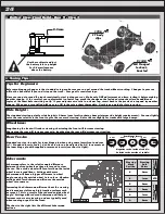


:: Tuning Tips
25
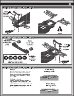
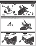
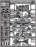
Rear Droop
Setting: 5mm
1
0
2 3 4 5
6 7 8
1
0
2 3 4 5
6 7 8
Front Droop
Setting: 6mm
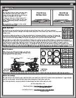
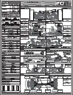
Droop:
The standard settings of 6mm front and 5mm
rear will work best in most cases. Droop is
measured just underneath the outer hinge pin
as shown in the photos to the right.
On bumpy or low grip surfaces, increase the
droop (going to a lower number on the droop
gauge), this will help increase traction and
consistency.
Droop adjustments of 0.5mm to 1mm can be
very effective on the track!
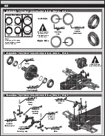
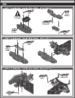
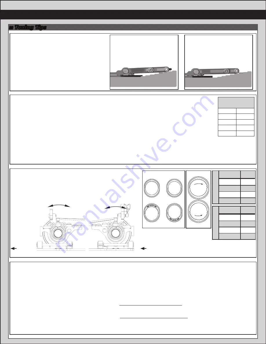
Anti-Roll Bar:
Anti-roll bars are only effective during roll (when the chassis leans from side to side when cornering).
Because of this they isolate a change in the suspensions spring rate in the corners only, and can be a very useful
tuning option.
Anti-roll bars stiffen the spring rate of the suspension during roll movements when cornering. The larger the
roll bar wire, the stiffer the spring rate will be in roll. The chart on the right shows the available anti-roll bar
sizes (as well as their corresponding colors) from the softest on the top, to the stiffest on the bottom.
The standard setup with a blue front anti-roll bar (1.4mm) and a white rear anti-roll bar (1.2mm), is a balanced starting point.
Changing the size of the front or rear anti-roll bars can help to make the chassis more consistent through the corner. Decreasing the
size of the front anti-roll bars will help to increase mid-corner steering, but will tend to be less stable in sweepers. This is a
typical setup for smaller tracks with tighter turns. Increasing the size of the front anti-roll bars will give more stability in the
sweepers, and is better for larger tracks with high speed corners. Increasing the size of the rear ant-roll bars will help add stability
into and through the corner in high traction conditions, but can make the car inconsistent in low traction, or bumpy, surfaces.
Anti Roll Bar
Color/Size Chart
Green
White
Gray
Blue
Yellow
1.1mm
1.2mm
1.3mm
1.4mm
1.5mm
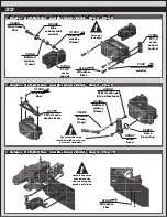
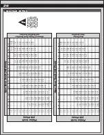
Front
Height
High
Mid-High
Mid
Low
Pos.
31
28
8
5
R
ear
Height
High
Mid-High
Mid
Low
Pos.
18
20
7
9
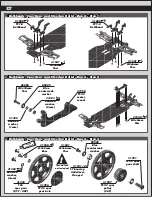
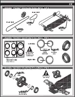
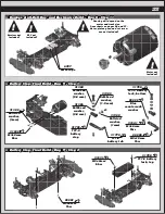
Belt Tension:
When altering the differential height, you will need
to adjust the tension of the belt. The following chart
shows suggested starting positions.
Note! Charts show left side cam positions from the left side of the car. Match right side cam position to left side cam position.
Left Side
Front
Left Side
Front
Belt Tension
Number
View from left
side of car
17
32
16
1
Cam Position
Mid-Low
Mid-High
Low
High
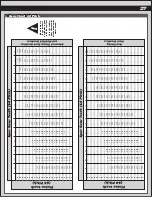
Motor Gearing:
The gear charts on the following page show final drive ratio numbers for the TC7.2. Refer to motor manufacturer’s suggested gear
ratio for starting point. You may need to adjust the gearing according to your track size.
The following formula’s can also be helpful in determining final drive ratios and pinion size.
TC7.2 Internal Ratio = 2.0
Final Drive Ratio = (# of Teeth Spur) x (Internal Ratio)
# of Teeth on Pinion
# of Teeth on Pinion = (# of Teeth on Spur) x (Internal Ratio)
Final Drive Ratio
Tighter
Looser
Tighter
Looser


