
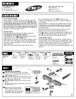


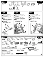


BAG C
REMOVE THESE
PARTS FOR:
Steps 4-5
TOOLS USED
step 3
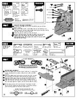
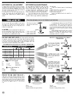
ASSEMBLE THE SHORT OUTDRIVE HUB
Slide one #6573 washer onto the #6575 bolt.
Apply a generous amount of #6588 black grease to the washer
on the side facing away from the bolt head.
Place six #6574 balls into the grease against the #6575 bolt
and washer. Add the other #6573 washer. The grease will hold
the balls in place during assembly, sandwiched between the
washers. See figure for installed view.
Slide the thrust assembly into the #3912 short outdrive hub,
bearing careful not to lose any of the balls.
Insert the #6575 bolt cover.
6588
6575 bolt
6573 washer
6574
6575 cover
1:1
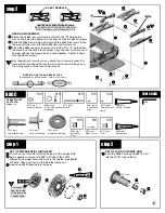
6909, qty 2
3/16 x 5/16 bearing
unflanged
6579, qty 4
diff drive ring
3976, qty 4
3/8 x 5/8 bearing
rubber sealed, unflanged
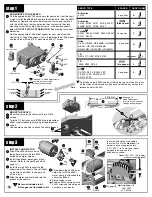
step 4
ASSEMBLE THE LONG OUTDRIVE HUB
Insert one #6909 bearing into the #3912 long hub.
Add a light coat of #6591
Assoc.
lube to the long hub
face where shown.
Place a #6579 diff drive ring and then the gear assembly
on the hub.
ASSEMBLE THE HUBS
Add a light coat of #6591
Assoc.
lube to the #3912 short hub face where shown.
Place a #6579 diff drive ring on the hub.
Push the #3912 short hub into the back side of the
differential ring gear. Center the diff bolt in the hub.
CHECK ALIGNMENT OF HUBS
Tighten the diff with your 5/64" Allen wrench, but not completely.
Rotate the diff hubs several times as you are tightening the bolt to check proper
alignment of the parts.
Read step 9 carefully.
7
8
6909
3912 long
6591
6579
6591
6579
3912 short
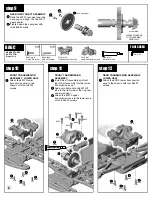
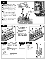
step 5
FINAL OUTDRIVE ASSEMBLY
Press the #3926 outdrive dust cap into
the #3912 long outdrive.
Place one #3911 outdrive shim on both
the long and short hubs.
Place one #3976 bearing over each
outdrive hub.
3912 long
3912 short
3911
3911
1:1
6
3911, qty 4
outdrive shim
1:1
1:1
9
5/64
6573 washer
3912 short
1:1
3976, qty 4
3/8 x 5/8 bearing
rubber sealed, unflanged
3976
3976
back side
front side
3926, qty 2
long outdrive
dust cap
3926 dust cap
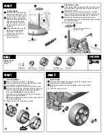
ADJUST THE DIFF
As you tighten the diff bolt, you will notice the T-nut ears moving closer to the bottom of the diff hub slot. This compresses the spring
behind the T-nut. The spring should be fully compressed at the same time the T-nut reaches the end of the slot.
Caution:
Pay close
attention to feeling when the spring is full compressed.
Do not overtighten the bolt.
When you feel the spring fully compressed, loosen the diff bolt 1/8 to 1/4 of a turn. No more, no less. Your diff should now operate very
smoothly when turning the hubs in opposite directions. After you have driven the car once, recheck the diff adjustment. Never adjust
the diff any other way.
Now assemble the second diff the same way.
10
IMPORTANT NOTE: STEPS 5, 6, 7 AND 8 INVOLVE SETTING THE MESH OF THE BEVEL GEARS.
Be sure to use only one
shim on each side of the
differential


