A8334 07/22
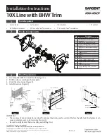
Installation Instructions
For installation assistance contact SARGENT
1-800-543-3658 • [email protected] • www.sargentlock.com
Copyright © 2022, ASSA ABLOY Access and Egress Hardware Group, Inc. All rights reserved.
Reproduction in whole or in part without the express written permission of ASSA ABLOY Access
and Egress Hardware Group, Inc. is prohibited.
2
11
3
4
5
6
8
7
9
1
14
12
13
15
10
Installation Instructions
2
Product Components
1
Tools Required
10X Line with BHW Trim
Fig.
Description
1
Inside escutcheon & lever assembly
2
Outside escutcheon & lever
assembly
3
Inside spring housing assembly
4
Screws - through-bolt (2) #10-32
x 1-1/4"
5
Lockbody assembly with mounting
plate
6
Outside spring housing assembly
7
Cylinder spacer
8
Cylinder
9
Key
10
Latch
11
Screws - latch (2) #8-32 x 3/4"
12
Screws - strike (2) #12-24 x 3/4"
13
Strike
14
Strike box (Optional)
15
Screws- through-bolt (3) #10-24 x
3-1/2"
3
Door Preparation
IMPORTANT
• The accuracy of door preparation is critical for proper functioning and security of this lever handle lock. Misalignment can
cause premature wear and a lessening of security.
• Be sure to verify backset before marking and drilling door.
1. Use template A8335 to mark the door (Figure 1).
2. Drill the door according to the template.
3. Verify the dimensions (Figure 2).
4. Install the strike (Figure 3)
DOOR
FRAME
Desired
height
above
floor
Template
Backset must
match latch
Door bevel
2x 7/16" (11mm) hole
1-1/8"
(29mm)
2-1/4"
(57mm)
1" (25mm)
hole
5/32" (4mm)
2-3/4"
(70mm)
Strike Box
Attaching Screws
#12 -24 x 3/4"
3x 1/2" (13mm) hole
4-3/4"
(120mm)
1-11/16"
(43mm)
2-1/8"
(54mm)
hole
5/8"
(16mm)
• 5/32" drill bit
• 1/2
"
drill bit
• 7/16" drill bit
• 1/8" drill bit
• #2 Phillips screwdriver
• T25 Security Torx
®
screwdriver
• T15 Security Torx
®
screwdriver


