background image

39

EN

EN

Notes

Intended use

Electrical locking devices of doors along escape routes are intended for use in 
commercial applications.

The product has been designed for the safeguarding of escape routes and has 
been tested according to the requirements of EltVTR. 

Deviating uses or device combinations not described in the approval are not 
permitted.

The product is only suitable for surface-mounted wall mounting.

The mounting, installation and commissioning of the product must be carried out 
by an electrician, with expertise in escape-door control systems, certified by 

ASSA 

ABLOY

 in accordance with the building authority requirements for electrome-

chanical locking on doors in escape routes. The electrician is obligated to apply 
the recognised rules of technology and test regulationsof the federal states and to 
keep this state of knowledge up to date.

It must be possible to disconnect the device from the power supply circuit at any 
time using an easily accessible energy-isolation device.

ASSA ABLOY Sicherheitstechnik GmbH

 can provide the necessary planning informa-

tion for approved solutions and the device combinations required for your 
application. The usage must be coordinated with the requirements of the 
inspection authorities. Contact the responsible inspection authority for this 
purpose.

Compliance with all relevant inspection authority requirements is mandatory for 
use, particularly with respect to the

 · coordination of the safety concept with the responsible inspection authority 

and 

 · modifications of door elements.

The device is suitable for mounting, installation, configuration and use as per 
these instructions. Any use beyond this is deemed as non-intended use; devices 
combinations which are not described are not permitted.

Содержание EffEff 1338-14

Страница 1: ...tname assaabloyopeningsolutions de Experience a safer and more open world Installations und Montageanleitung Installation and mounting instructions N O T A U F DE Seite 2 EN Page 34 Fluchtt r Steuerte...

Страница 2: ...einschlie lich aller ihrer Teile ist urheberrechtlich gesch tzt Jede Verwertung bzw Ver nderung au erhalb der engen Grenzen des Urheberrechtsgesetzes ist ohne Zustimmung von ASSA ABLOY Sicherheitstec...

Страница 3: ...riegelungselemente 11 Profilhalbzylinder 12 Den Profilzylinder auswechseln 13 Konfiguration 14 Anschlussplan 14 Einstellm glichkeiten am Fluchtt r Steuerterminal 15 Betriebsart 2 Busbetrieb 19 Bus Ans...

Страница 4: ...n 27 Alarmursache ermitteln 27 Wartung und berpr fung 28 Wartung 28 Wiederkehrende Pr fung 28 Zertifizierung 28 Technische Daten 29 Elektrische Daten 29 Prim r 29 Sekund r 29 Gew hrleistung Entsorgung...

Страница 5: ...nde Kenntnisse zum Produkt ben tigt die nicht in dieser Anleitung beschrieben werden Bedeutung der Symbole Gefahr Sicherheitshinweis Nichtbeachtung f hrt zu Tod oder schweren Verletzungen Warnung Sich...

Страница 6: ...hmigung Lebensgefahr durch fehlerhafte Inbetriebnahme Um die Produktsicherheit zu gew hrleisten muss die Inbetriebnahme durch eine sachkundige Person durchgef hrt werden ASSA ABLOY Sicherheitstechnik...

Страница 7: ...nerkannten Regeln der Technik Pr fverord nungen der Bundesl nder anzuwenden und diesen Kenntnisstand aktuell zu halten Das Ger t muss jederzeit durch eine leicht zug ngliche Trennvorrichtung vom Verso...

Страница 8: ...tt r Steuerterminal 1338 20 besitzt zus tzlich zur gesamten Steuerelekt ronik ein integriertes Netzteil das sowohl die Elektronik des Steuerterminals als auch die Verriegelungselemente mit der n tigen...

Страница 9: ...standes durch ein akustisches und optisches Signal Jeweils ein Relaiskontakt f r zus tzliche Verriegelt Entriegelt Anzeigen sowie f r eine externe Alarmmeldung Betrieb in Kombination mit einem Bedient...

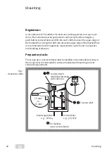
Страница 10: ...n 850mm ber OKFF N heres regelt die jeweilige Landesbauordnung Vorbereitende Arbeiten Das Fluchtt r Steuerterminal ist in unmittelbarer N he der Fluchtt r zu montie ren Es ist f r die Aufputz Wandmont...

Страница 11: ...1338 wird durch die linke Kabeleinf hrung ausschlie lich die Netzzuleitung gef hrt F r alle Steuerleitungen wird die rechte Kabeleinf hrung benutzt Leitungsauswahl Die Steuerleitungen d rfen maximal 3...

Страница 12: ...tauscht werden In das Fluchtt r Steuerterminal k nnen nur Profilhalbzylinder der Bauform 90 links mit einer L nge von 30mm bis 35mm eingesetzt werden 90 Abb 3 Wechseln des Profilhalbzylinders Schalter...

Страница 13: ...erschaltelemente nicht durch den Schlie hebel des Zylinders besch digt werden 6 Schieben Sie den neuen Schlie zylinder von der Geh useinnenseite durch das Geh use 7 Fixieren Sie den Schlie zylinder mi...

Страница 14: ...der Brandmeldeanlage nach EltVTR Anschluss Brandmeldeanlage nach DIN EN 13637 2015 ber 1386BMA 01 Anschlussmodul Brandmeldeanlage 24 VDC Keine Brandmeldeanlage angeschlossen Br cke einbauen Modelle 13...

Страница 15: ...Ein akustischer Voralarm wird vor einem Alarm ausgel st Der Alarmkontakt sowie die optische Anzeige werden vom Voralarm nicht beeinflusst offen Voralarm ausgeschaltet Ein akustischer Voralarm wird unt...

Страница 16: ...n den Klemmen 11 12 angeschlossen ist m glich 3 ON werkseitig Die Dauerentriegelung erfolgt sofort nach Bet tigung OFF die Dauerentriegelung erfolgt erst nach 5 Sekunden st ndiger Bet tigung 4 ON werk...

Страница 17: ...4 Sekunden Raster Voralarm Ein Voralarm bleibt bei ge ffneter T r f r die am Drehschalter S2 eingestellte Zeit aktiviert Danach wird Alarm ausgel st Tab 2 DIP Schalter S4 1 Drehschalter S2 in Betrieb...

Страница 18: ...tellen ON OFF 1 2 Die Beleuchtung ist ausgeschaltet ON OFF 1 2 Leuchtet gr n wenn die T r entriegelt ist ON OFF 1 2 Ist dunkel wenn die T r entriegelt ist Leuchtet rot wenn die T r verriegelt ist ON O...

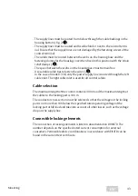
Страница 19: ...bar separate Anleitung D01165 Bus Anschluss Ein TSB Controller 970 TSBC wird ber eine Zwei Draht Busleitung an den Klemmen Data und GND Abb 4 Seite 14 angeschlossen Achtung Zerst rungsgefahr und Funkt...

Страница 20: ...eingestellten Adressbereich addieren Einschr nkung 0 0 Nicht bei Drehschalter S3 auf Position 0 1 1 2 2 9 9 Nicht bei Drehschalter S3 auf Position 7 A 10 B 11 C 12 F 15 Beispiel Drehschalter S3 auf 6...

Страница 21: ...ung der Verriegelung im Gefahrenfall zu verwenden 2 Lassen Sie den ordnungsgem en Einbau und die Funktionsf higkeit der elektrischen Fluchtt rverriegelung durch einen Sachverst ndigen feststellen Auto...

Страница 22: ...Voralarm und Alarm Wird die T r ber die eingestellte Kurzfreigabezeit hinaus offen gehalten wird zun chst ein Voralarm ausgel st und schlie lich ein Alarm Ein Voralarm wird durch Schlie en der T r bee...

Страница 23: ...onfiguration der Dauerentriegelung Die Dauerentriegelung ber den Schl sseltaster muss ber eine Steckbr cke aktiviert sein Tab 1 Seite 15 ber DIP Schalter S4 3 Tab 2 Seite 16 kann eingestellt werden ob...

Страница 24: ...n 9 10 ausgel st falls die T r nicht geschlossen ist Quittieren eines Alarms Ein ausgel ster Alarm muss bei geschlossener T r quittiert werden Die T r wird verriegelt die rote und die gelbe LED leucht...

Страница 25: ...erden Achtung Fehlfunktion wenn der Brandmeldekontakt nicht geschlossen ist Wird kein Brandmeldeanlage angeschlossen so m ssen die Anschlussklemmen 13 14 mit einer Drahtbr cke geschlossen werden Wurde...

Страница 26: ...arm nach Voralarm bei offener T r Gefahrenalarm Der Gefahrenalarm kann ausgel st werden durch die Bet tigung des NOT AUF Schalters durch eine Brandmeldeanlage durch einen innerhalb von drei Sekunden e...

Страница 27: ...aft 4 Verriegeln Sie die T r Der Alarmspeicher ist gel scht Alarmursache ermitteln Solange ein Alarm nicht zur ckgesetzt wurde leuchtet die gr ne LED im Verh ltnis 1 1 Solange der Alarm nicht zur ckge...

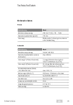
Страница 28: ...von der Pflicht zu regelm ig wiederkehrender Pr fung der Fluchtt rverriegelung Wiederkehrende Pr fung Ein Sachkundiger muss eine j hrliche berpr fung der T ren in Rettungswegen mit elektrischen Verri...

Страница 29: ...externe Verbraucher max 450mA Sicherung F1 Platine Steuerteil 1A tr ge Kleinstsicherung Serie 372 374 Wickmann Typ TR 5 Sicherung F2 Platine Steuerteil 0 1A tr ge Kleinstsicherung Serie 372 374 Wickma...

Страница 30: ...ngsmaterialien m ssen der Wiederverwendung zugef hrt werden WEEE Reg Nr DE 69404980 Das Produkt ist nach dem Gebrauch als Elektronikschrott ordnungsgem zu entsorgen und zur stofflichen Wiederverwendun...

Страница 31: ...31 DE Checkliste Pr fung vor der Erstinbetriebnahme...

Страница 32: ...eren Sie das Verriegelungselement Bezeichnung Ja Nein Die roten LEDs leuchten Die T r ist sicher verriegelt manuell pr fen 3 Bet tigen Sie die Nottaste Bezeichnung Ja Nein Die T r ist entriegelt manue...

Страница 33: ...sche Alarmsignal spricht an Gefahrenmeldeanlage pr fen und dokumentieren Diese Funktionspr fung entf llt wenn keine Gefahrenmeldeanlage zum Beispiel Brandmeldeanlage angeschlossen ist 1 Aktivieren Sie...

Страница 34: ...This document and all its parts are copyrighted Any use or changes outside the strict limits of the copyright are prohibited and liable to prosecution unless prior consent has been obtained from ASSA...

Страница 35: ...ements 43 Profile half cylinder 44 Replacing the profile cylinder 45 Configuration 46 Connection diagram 46 Setting options on the escape door control terminal 47 Mode 2 bus operation 51 Bus connectio...

Страница 36: ...ermining the cause of the alarm 59 Maintenance and inspection 60 Maintenance 60 Recurring inspection 60 Certification 60 Technical data 61 Electrical data 61 Primary 61 Secondary 61 Warranty disposal...

Страница 37: ...tallation commissioning and maintenance which is not described in this manual Meaning of the symbols Danger Safety notice Failure to observe these warnings will lead to death or severe injury Warning...

Страница 38: ...is prerequi site for the approval Danger to life due to faulty commissioning In order to ensure the safety of the product commissioning must be performed by a qualified person ASSA ABLOY Sicherheitste...

Страница 39: ...st regulationsof the federal states and to keep this state of knowledge up to date It must be possible to disconnect the device from the power supply circuit at any time using an easily accessible ene...

Страница 40: ...l 1338 20 In addition to the entire control electronics the escape door control terminal 1338 20 has an integrated mains adapter which supplies both the electronics of the control terminal and the loc...

Страница 41: ...an optical and audible signal One relay contact each for additional Locked Unlocked displays and for an external alarm message Operation in combination with a control panel 1332 10 11 Model 1338 20 13...

Страница 42: ...loor is recommended Further regulatory requirements can be found in respective local building ordinances Preparatory tasks The escape door control terminal must be installed in the immediate vicinity...

Страница 43: ...nly the power supply line is routed through the left cable inlet The right cable inlet is used for all control cables Cable selection The maximum length of the control cables is 300 m and the maximum...

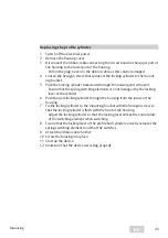
Страница 44: ...ylinder can be replaced Only profile half cylinder design 90 left with a length of 30 mm to 35 mm can be used in the escape door control terminal 90 Fig 3 Replacing the profile half cylinder Button Bu...

Страница 45: ...itching elements are not damaged by the locking lever of the cylinder 6 Push the new locking cylinder through the housing from the inside of the housing 7 Fix the locking cylinder to the mounting brac...

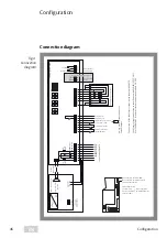
Страница 46: ...ntact max 24 V 1A Models 1338 20 21 1340 20 21 Door control bus DC BUS Relay Alarm max 24 V 1 A External emergency release e g fire alarm system Temporary release Permanent release clock switch EMERGE...

Страница 47: ...e alarm switched on An acoustic pre alarm is triggered before an alarm The pre alarm does not affect the alarm contact or the visual display open Pre alarm switched off An acoustic pre alarm is suppre...

Страница 48: ...ton connected to terminals 11 12 3 ON factory default Permanent release takes place immediately after actuation OFF Permanent release only takes place after 5 seconds of contin uous actuation 4 ON fa...

Страница 49: ...conds 4 second grid Pre alarm A pre alarm remains activated when the door is open for the time set on rotary switch S2 Then an alarm is triggered Tab 2 DIP switch S4 1 Rotary switch S2 in mode 2 Set p...

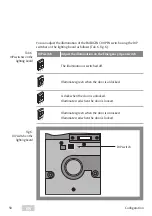
Страница 50: ...ergency Open switch ON OFF 1 2 The illumination is switched off ON OFF 1 2 Illuminates green when the door is unlocked ON OFF 1 2 Is dark when the door is unlocked Illuminates red when the door is loc...

Страница 51: ...970 TSBC separate manual D01165 Bus connection A DCB controller 970 TSBC is connected to the terminals Data and GND Fig 4 page 46 via a two wire bus line Important Risk of destruction and malfunction...

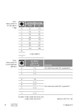
Страница 52: ...address Add to set address range Limitation 0 0 Not with rotary switch S3 in position 0 1 1 2 2 9 9 Not with rotary switch S3 in position 7 A 10 B 11 C 12 F 15 Example rotary switch S3 set to 6 and ro...

Страница 53: ...ust be taken with regard to the elements for releasing the locking in the event of danger 2 Have correct installation and function of the escape door locking system checked by technical specialists Au...

Страница 54: ...re alarm and alarm If the door is kept open beyond the set temporary release time a pre alarm is triggered rst and then an alarm A pre alarm is ended by closing the door An alarm must be acknowledged...

Страница 55: ...DCB controller 970 TSBC Permanent release configuration The permanent release via the key pushbutton must be activated via a jumper Tab 1 page 47 DIP switch S4 3 Tab 2 page 48 can be used to set whet...

Страница 56: ...r The sequence of functions is triggered via terminals 9 10 if the door is not closed Acknowledging an alarm A triggered alarm must be acknowledged when the door is closed The door is locked the red a...

Страница 57: ...ted via DIP switch S4 4 Important Malfunction if the fire alarm contact is not closed If no fire alarm system is connected the connecting terminals 13 14 must be connected with a jumper If the alarm w...

Страница 58: ...alarm alarm after pre alarm on open door Danger alarm The danger alarm can be triggered by actuating the EMERGENCY OPEN switch by a fire alarm system due to an unsuccessful locking attempt within thre...

Страница 59: ...door The alarm memory is cleared Determining the cause of the alarm As long as an alarm has not been reset the green LED lights up in a ratio of 1 1 As long as the alarm has not been reset the cause...

Страница 60: ...from the obligation to subject escape door locking systems to inspection on a regular basis Recurring inspection A technical specialist must carry out an annual inspection of escape route doors with...

Страница 61: ...fuse F1 control part board 1 A slow blow small safety fuse series 372 374 Wickmann type TR 5 Safety fuse F2 control part board 0 1A slow blow small safety fuse series 372 374 Wickmann type TR 5 Conta...

Страница 62: ...claration Packaging materials must be recycled WEEE reg no DE 69404980 The product is to be properly disposed of as electronic scrap after use and to be dropped off at a local collection point free of...

Страница 63: ...63 EN EN Check list Testing before initial operation...

Страница 64: ...tivate the locking element Identifier Yes No Do the red LEDs light up Is the door securely locked test manually 3 Press the emergency button Identifier Yes No Is the door released test manually Canthe...

Страница 65: ...ntegrated acoustic alarm sound Checking and documenting the hazard warning system This function test is not necessary if no hazard alarm system for example fire alarm system is connected 1 Activate th...

Страница 66: ...66 EN...

Страница 67: ...67 EN EN...

Страница 68: ...icherer und geborgener zu f hlen und eine offenere Welt zu erleben ASSA ABLOY Sicherheitstechnik GmbH Bildstockstra e 20 72458 Albstadt DEUTSCHLAND Tel 49 7431 123 0 Fax 49 7431 123 240 albstadt assaa...

Отзывы: