background image

1 1

1 1

1 1

1 1

1 1

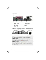
1.4 I/O Panel

1.4 I/O Panel

1.4 I/O Panel

1.4 I/O Panel

1.4 I/O Panel

1

PS/2  Mouse  Port  (Green)

7

USB 2.0  Ports  (USB01)

2

Parallel  Port

8

USB 2.0  Ports  (USB23)

3

RJ-45  Port

9

VGA Port

4

Line  In  (Light Blue)

10

COM Port

5

Line  Out  (Lime)

11

PS/2  Keyboard  Port  (Purple)

6

Microphone  (Pink)

1

3

7

8

5

4

6

9

10

11

2

LAN Port

ACT/LINK

    LED

SPEED

  LED

* There are two LED next to the LAN port. Please refer to the table below for the LAN port LED

   indications.


LAN Port LED Indications

       Activity/Link LED

SPEED LED

Status        Description          Status          Description

Off           No Activity          Off            10Mbps connection

Blinking    Data Activity       Green        100Mbps connection

  To enable Multi-Streaming function, you need to connect a front panel audio cable to the front

  panel audio header. After restarting your computer, you will find “VIA HD Audio Deck” tool on

  your system. Please follow below instructions according to the OS you install.


For Windows

®

 XP OS:

  Please click “VIA HD Audio Deck” icon               , and click “Speaker”. Then you are allowed to

  select “2 Channel” or “4 Channel”. Click “Power” to save your change.


For Windows

®

 7 / Vista

TM

 OS:

  Please click “VIA HD Audio Deck” icon               , and click “Advanced Options” on the left side

  on the bottom. In “Advanced Options” screen, select “Independent Headphone”, and click

  “OK” to save your change.

Содержание PV530

Страница 1: ...1 1 1 1 1 PV530 User Manual Version 1 0 Published April 2010 Copyright 2010 ASRock INC All rights reserved ...

Страница 2: ... or implied including but not limited to the implied warran ties or conditions of merchantability or fitness for a particular purpose In no event shall ASRock its directors officers employees or agents be liable for any indirect special incidental or consequential damages including damages for loss of profits loss of business loss of data interruption of business and the like even if ASRock has be...

Страница 3: ... Serial ATA SATA Serial ATAII SATAII Hard Disks Installation 19 2 9 Driver Installation Guide 20 2 10 Untied Overclocking Technology 20 3 BIOS S 3 BIOS S 3 BIOS S 3 BIOS S 3 BIOS SETUP UTILITY ETUP UTILITY ETUP UTILITY ETUP UTILITY ETUP UTILITY 21 21 21 21 21 3 1 Introduction 21 3 1 1 BIOS Menu Bar 21 3 1 2 Navigation Keys 22 3 2 Main Screen 22 3 3 OC Tweaker Screen 23 3 4 Advanced Screen 26 3 4 1...

Страница 4: ...upport 4 Software Support 4 Software Support 4 Software Support 39 39 39 39 39 4 1 Install Operating System 39 4 2 Support CD Information 39 4 2 1 Running Support CD 39 4 2 2 Drivers Menu 39 4 2 3 Utilities Menu 39 4 2 4 Contact Information 39 ...

Страница 5: ...the BIOS software might be updated the content of this manual will be subject to change without notice In case any modifications of this manual occur the updated version will be available on ASRock website without further notice You may find the latest VGA cards and CPU support lists on ASRock website as well ASRock website http www asrock com If you require technical support related to this mothe...

Страница 6: ...PCI Express 2 0 x16 slot blue x8 mode 1 x PCI slot Graphics VIA Chrome9 HD DX9 Graphics Pixel Shader 2 0 DirectX 9 0 Max shared memory 512MB see CAUTION 3 Supports D Sub with max resolution up to 2048x1536 75Hz Audio 5 1 CH HD Audio VIA VT1705 Audio Codec LAN Atheros PCIEx1 LAN AR8132L Speed 10 100 Ethernet Supports Wake On LAN Rear Panel I O I O Panel 1 x PS 2 Mouse Port 1 x PS 2 Keyboard Port 1 ...

Страница 7: ... Sensing Monitor Chassis Temperature Sensing CPU Chassis Power Fan Tachometer Voltage Monitoring 12V 5V 3 3V Vcore OS Microsoft Windows 7 VistaTM XP compliant Certifications FCC CE WHQL ErP EuP Ready ErP EuP ready power supply is required see CAUTION 10 For detailed product information please visit our website http www asrock com WARNING Please realize that there is a certain risk involved with ov...

Страница 8: ...h this tool and save the new BIOS file to your USB flash drive floppy disk or hard drive then you can update your BIOS only in a few clicks without prepar ing an additional floppy diskette or other complicated flash utility Please be noted that the USB flash drive or hard drive must use FAT32 16 12 file system 7 The software name itself OC DNA literally tells you what it is capable of OC DNA an ex...

Страница 9: ... shall be under 1 00W in off mode condition To meet EuP standard an EuP ready motherboard and an EuP ready power supply are required According to Intel s suggestion the EuP ready power supply must meet the standard of 5v standby power efficiency is higher than 50 under 100 mA current consumption For EuP ready power supply selection we recommend you checking with the power supply manufacturer for m...

Страница 10: ...2 Blue 9 USB 2 0 Header USB4_5 Blue 21 VIA VX900 Chipset 10 BIOS SPI Chip 22 USB_PWR2 Jumper 11 Chassis Fan Connector CHA_FAN1 23 CPU Fan Connector CPU_FAN1 12 System Panel Header PANEL1 White 1 PS2_USB_PWR1 SPEAKER1 1 HD_AUDIO1 PANEL 1 HDLED RESET PLED PWRBTN 1 CMOS Battery 4Mb BIOS 1 AUDIO CODEC 17 0cm 6 7 in 21 6cm 8 5 in Super IO 1 2 4 5 7 6 8 9 10 12 13 14 11 15 16 17 18 3 FSB800 DDRII_1 64 b...

Страница 11: ...atus Description Off No Activity Off 10Mbps connection Blinking Data Activity Green 100Mbps connection To enable Multi Streaming function you need to connect a front panel audio cable to the front panel audio header After restarting your computer you will find VIA HD Audio Deck tool on your system Please follow below instructions according to the OS you install For Windows XP OS Please click VIA H...

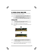
Страница 12: ...2 2 Pre installation Precautions 2 2 Pre installation Precautions 2 2 Pre installation Precautions 2 2 Pre installation Precautions Take note of the following precautions before you install motherboard components or change any motherboard settings 1 Unplug the power cord from the wall socket before touching any component 2 To avoid damaging the motherboard components due to static electricity NEVE...

Страница 13: ...the same time You can choose to install either DDR2 or DDR3 memory module Installing a DIMM Installing a DIMM Installing a DIMM Installing a DIMM Installing a DIMM Please make sure to disconnect power supply before adding or removing DIMMs or the system components Step 1 Unlock a DIMM slot by pressing the retaining clips outward Step 2 Align a DIMM on the slot such that the notch on the DIMM match...

Страница 14: ...ion card Installing an expansion card Installing an expansion card Installing an expansion card Step 1 Before installing the expansion card please make sure that the power supply is switched off or the power cord is unplugged Please read the documentation of the expansion card and make necessary hardware settings for the card before you start the installation Step 2 Remove the system unit cover if...

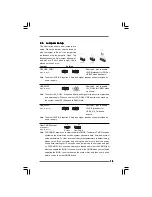
Страница 15: ...elect 5V_DUAL USB devices can wake up the system under S3 Suspend to RAM state USB_PWR3 Short pin2 pin3 to enable see p 10 No 17 5VSB standby for USB4_5 6_7 wake up events Note To select 5VSB it requires 2 Amp and higher standby current provided by power supply Clear CMOS Jumper CLRCMOS1 see p 10 No 14 Note CLRCMOS1 allows you to clear the data in CMOS The data in CMOS includes system setup inform...

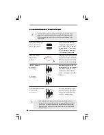
Страница 16: ... and Connectors Onboard headers and connectors are NOT jumpers Do NOT place jumper caps over these headers and connectors Placing jumper caps over the headers and connectors will cause permanent damage of the motherboard Serial ATAII Connectors These Serial ATAII SATAII SATAII_1 see p 10 No 20 connectors support SATAII SATAII_2 see p 10 No 19 or SATA hard disk for internal storage devices The curr...

Страница 17: ...PU fan cable 3 pin CPU_FAN1 to this connector and match see p 10 No 23 the black wire to the ground pin ATX Power Connector Please connect an ATX power 24 pin ATXPWR1 supply to this connector see p 10 No 3 A Connect Mic_IN MIC to MIC2_L B Connect Audio_R RIN to OUT2_R and Audio_L LIN to OUT2_L C Connect Ground GND to Ground GND D MIC_RET and OUT_RET are for HD audio panel only You don t need to co...

Страница 18: ...sk may fail to run at SATAII mode Western Digital If pin 5 and pin 6 are shorted SATA 1 5Gb s will be enabled On the other hand if you want to enable SATAII 3 0Gb s please remove the jumpers from pin 5 and pin 6 SAMSUNG If pin 3 and pin 4 are shorted SATA 1 5Gb s will be enabled On the other hand if you want to enable SATAII 3 0Gb s please remove the jumpers from pin 3 and pin 4 HITACHI Please use...

Страница 19: ...lation This motherboard adopts VIA VX900 chipset that supports Serial ATA SATA Serial ATAII SATAII hard disks You may install SATA SATAII hard disks on this motherboard for internal storage devices This section will guide you to install the SATA SATAII hard disks STEP1 Install the SATA SATAII hard disks into the drive bays of your chassis STEP2 Connect the SATA power cable to the SATA SATAII hard ...

Страница 20: ... overclocking but PCI buse is in the fixed mode so that FSB can operate under a more stable overclocking environment Please refer to the warning on page 7 for the possible overclocking risk before you apply Untied Overclocking Technology 2 9 2 9 2 9 2 9 2 9 Driver Installation Guide Driver Installation Guide Driver Installation Guide Driver Installation Guide Driver Installation Guide To install t...

Страница 21: ... chassis You may also restart by turning the system off and then back on Because the BIOS software is constantly being updated the following BIOS setup screens and descriptions are for refer ence purpose only and they may not exactly match what you see on your screen 3 1 1 3 1 1 3 1 1 3 1 1 3 1 1 BIOS Menu Bar BIOS Menu Bar BIOS Menu Bar BIOS Menu Bar BIOS Menu Bar The top of the screen has a menu...

Страница 22: ...n Screen Main Screen Main Screen When you enter the BIOS SETUP UTILITY the Main screen will appear and display the system overview System Time Hour Minute Second Use this item to specify the system time System Date Day Month Date Year Use this item to specify the system date BIOS SETUP UTILITY Main OC Tweaker H W Monitor Boot Security Exit Advanced System Overview System Time System Date 00 09 Fri...

Страница 23: ... screen you can set up overclocking features Overclock Mode Use this to select Overclock Mode The default value is Auto Configura tion options Auto CPU PCIE Sync CPU PCIE Async and Optimized CPU Frequency MHz Use this option to adjust CPU frequency PCIE Frequency MHz Use this option to adjust PCIE frequency Boot Failure Guard Enable or disable the feature of Boot Failure Guard Boot Failure Guard C...

Страница 24: ...for DDR2 The default value is Auto DRAM tRP This controls the number of DRAM clocks for TRP Configuration options 4T to 11T for DDR3 2T to 9T for DDR2 The default value is Auto DRAM tRAS This controls the number of DRAM clocks for TRAS Configuration options 15T to 30T for DDR3 5T to 20T for DDR2 The default value is Auto DRAM tRFC This controls the number of DRAM clocks for TRFC Configuration opti...

Страница 25: ...ge Configuration options 1 48V to 1 88V for DDR3 1 80V to 2 21V for DDR2 The default value of this feature is Auto Chipset Voltage Use this to select chipset Voltage Configuration options Auto 1 20V to 1 35V The default value of this feature is Auto VTT Voltage Use this to select VTT Voltage Configuration options Auto 1 05V to 1 10V The default value of this feature is Auto Would you like to save ...

Страница 26: ...set the configurations for the following items CPU Configuration Chipset Configuration ACPI Configuration Storage Configuration PCIPnP Configuration SuperIO Configuration and USB Configuration ASRock Instant Flash ASRock Instant Flash is a BIOS flash utility embedded in Flash ROM This convenient BIOS update tool allows you to update system BIOS without entering operating systems first like MS DOS ...

Страница 27: ...rmal control mechanism Select Screen Select Item Change Option F1 General Help F9 Load Defaults F10 Save and Exit ESC Exit v02 54 C Copyright 1985 2005 American Megatrends Inc Advanced Select Screen Select Item Change Option F1 General Help F9 Load Defaults F10 Save and Exit ESC Exit CPU Ratio Setting VIA Pv530 Processor 1800MHz Frequency 1 80GHz Cache L1 128 KB Cache L2 128 KB Ratio Status Unlock...

Страница 28: ...ers Primary Graphics Adapter This item shows the primary graphics adapter The default value is PCI Configuration options Onboard PCI and PCI Express Onboard VGA Share Memory This allows you to set onboard VGA share memory feature The default value is Auto Configuration options Auto 16MB 32MB 64MB 128MB 256MB and 512MB PCIE Target Link Speed Use this item to set PCIE target link speed Configuration...

Страница 29: ...se this item to enable or disable the feature Check Ready Bit Restore on AC Power Loss This allows you to set the power state after an unexpected AC Power loss If Power Off is selected the AC Power remains off when the power recovers If Power On is selected the AC Power resumes and the system starts to boot up when the power recovers Ring In Power On Use this item to enable or disable Ring In sign...

Страница 30: ...4 MultiWord DMA 2 Ultra DMA 5 Supported BIOS SETUP UTILITY Storage Configuration Enable Disable onboard SATA controller v02 54 C Copyright 1985 2005 American Megatrends Inc Advanced OnBoard SATA Controller Enabled Select Screen Select Item Change Option F1 General Help F9 Load Defaults F10 Save and Exit ESC Exit Select Screen Select Item Change Option F1 General Help F9 Load Defaults F10 Save and ...

Страница 31: ...re is enabled it will enhance hard disk performance by reading or writing more data during each transfer PIO Mode Use this item to set the PIO mode to enhance hard disk performance by optimizing the hard disk timing DMA Mode DMA capability allows the improved transfer speed and data integrity for compatible IDE devices S M A R T Use this item to enable or disable the S M A R T Self Monitoring Anal...

Страница 32: ... PCI expansion cards specifications require other settings PCI IDE BusMaster Use this item to enable or disable the PCI IDE BusMaster feature BIOS SETUP UTILITY Advanced PCI PnP Settings Value in units of PCI clocks for PCI device latency timer register Select Screen Select Item Change Option F1 General Help F9 Load Defaults F10 Save and Exit ESC Exit v02 54 C Copyright 1985 2005 American Megatren...

Страница 33: ...will show the EPP version in the following item EPP Version Configuration options Normal Bi Directional and ECP EPP EPP Version Use this item to set the EPP version Configuration options 1 9 and 1 7 ECP Mode DMA Channel Use this item to set the ECP mode DMA channel Configuration options DMA0 DMA1 and DMA3 Parallel Port IRQ Use this item to set the IRQ for the parallel port Configuration options IR...

Страница 34: ...isable the USB 2 0 support Legacy USB Support Use this option to select legacy support for USB devices There are four configuration options Enabled Auto Disabled and BIOS Setup Only The default value is Enabled Please refer to below descriptions for the details of these four options Enabled Enables support for legacy USB Auto Enables legacy support if USB devices are connected Disabled USB devices...

Страница 35: ...F N A Main OC Tweaker Advanced Boot Security Exit H W Monitor Enable Disable CPU Quiet Fan Function CPU Quiet Fan Disabled Chassis Fan Full On CPU Quiet Fan This item allows you to identify the temperature of CPU fan If you set this option as Disabled the CPU fan will operate in full speed If you set this option as Enabled you will find the items Target CPU Temperature and Target Fan Speed appear ...

Страница 36: ...option only appears when you enable the option Full Screen Logo Configuration options Auto EuP Scenery and ASRock The default value is Auto BIOS SETUP UTILITY Main OC Tweaker Advanced H W Monitor Security Exit Boot Settings Configure Settings during System Boot Select Screen Select Item Enter Go to Sub Screen F1 General Help F9 Load Defaults F10 Save and Exit ESC Exit v02 54 C Copyright 1985 2005 ...

Страница 37: ...ll or Change the password Select Screen Select Item Enter Change F1 General Help F10 Save and Exit ESC Exit F9 Load Defaults v02 54 C Copyright 1985 2005 American Megatrends Inc Security Change Supervisor Password Change User Password Security Settings Supervisor Password Not Installed User Password Not Installed Boot From Onboard LAN Use this item to enable or disable the Boot From Onboard LAN fe...

Страница 38: ...it Screen Exit Screen Exit Screen Exit Screen Save Changes and Exit When you select this option it will pop out the following message Save configuration changes and exit setup Select OK to save the changes and exit the BIOS SETUP UTILITY Discard Changes and Exit When you select this option it will pop out the following message Dis card changes and exit setup Select OK to exit the BIOS SETUP UTILIT...

Страница 39: ...port CD Running The Support CD To begin using the support CD insert the CD into your CD ROM drive The CD automatically displays the Main Menu if AUTORUN is enabled in your computer If the Main Menu did not appear automatically locate and double click on the file ASSETUP EXE from the BIN folder in the Support CD to display the menus 4 2 2 4 2 2 4 2 2 4 2 2 4 2 2 Drivers Menu Drivers Menu Drivers Me...

Отзывы: