


17
2.6 Onboard Headers and Connectors
Onboard headers and connectors are NOT jumpers. Do NOT place
jumper caps over these headers and connectors. Placing jumper caps
over the headers and connectors will cause permanent damage of the
motherboard!
SATA2 Connectors
These two Serial ATA2
(SATA2_1, SATA2_2: see p.8, No. 14)
(SATA2) connectors support
SATA data cables for internal
storage devices. The current
SATA2 interface allows up to
3.0 Gb/s data transfer rate.
USB 2.0 Connectors
Besides two default USB 2.0
(9-pin USB2_2_3)
ports on the I/O panel, there
(see p.8 No. 19)
are two USB 2.0 connectors on
this motherboard. Each USB 2.0
(9-pin USB2_4_5)
connector can support two USB
(see p.8 No. 3)
ports.
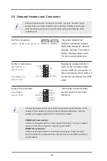
System Panel Header
This header accommodates
(9-pin PANEL1)
several system front panel
(see p.8 No. 20)
functions.
Connect the power switch, reset switch and system status indicator on the
chassis to this header according to the pin assignments below. Note the
positive and negative pins before connecting the cables.
PWRBTN (Power Switch):
Connect to the power switch on the chassis front panel. You may configure
the way to turn off your system using the power switch.
RESET (Reset Switch):
Connect to the reset switch on the chassis front panel. Press the reset
switch to restart the computer if the computer freezes and fails to perform a
normal restart.
SATA2_2 SATA2_1
DUMMY
GND
GND
+B
-B
+A
-A
USB_PWR
USB_PWR
1
GND
RESET#
PWRBTN#
PLED-
PLED+
GND
HDLED-
HDLED+
1
GND


