background image

2 2

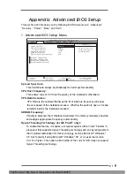
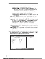
Chipset Configuration:

AGP Aperture Size:

 It refers to a section of the PCI memory address range

used for graphics memory. It is recommended to leave this field at the

default value unless your AGP card requires other sizes.

OnBoard VGA Share Memory: 

This allows you to select the size of share

memory for onboard VGA. Onboard VGA will get better resolution if larger

size of share memory is selected. Please do not select [Disabled] if PCI

graphics card is not inserted.

USB Controller:

  Use this to enable or disable the use of USB controller.

USB Device Legacy Support: 

 Use this to enable or disable support to emulate

legacy I/O devices such as mouse, keyboard,... etc.

DRAM CAS# Latency:

This parameter controls the latency between the read command and the

time the data available.

AMIBIOS SETUP UTILITY - VERSION 3.31a

Advanced

AGP Aperture Size
Onboard VGA Share Memory

USB Controller
USB Device Legacy Support

DRAM CAS# Latency

[

Setup Help

]

F1:Help

Esc:Previous Menu

F9:Setup Defaults
F10:Save & Exit

+/-:Change Values

Enter:Select

Sub-Menu

:Select Item

Chipset Configuration

32MB

Enabled
Disabled

Auto

<Enter> to select the
size of mapped memory
for graphics data.

64MB

This Manual: http://www.manuallib.com/file/2630978

Содержание GE PRO-HT

Страница 1: ...nualLib com ManualLib com collects and classifies the global product instrunction manuals to help users access anytime and anywhere helping users make better use of products Home http www manuallib com Chinese http www shuomingshuku com This Manual http www manuallib com file 2630978 ...

Страница 2: ...1 GE Pro HT GE Pro M2 User Manual Version 3 0 Published July 2003 Copyright 2003 ASRock INC All rights reserved This Manual http www manuallib com file 2630978 ...

Страница 3: ...e and should not be constructed as a commitment by ASRock ASRock assumes no responsibility for any errors or omissions that may appear in this manual With respect to the contents of this manual ASRock does not provide warranty of any kind either expressed or implied including but not limited to the implied warran ties or conditions of merchantability or fitness for a particular purpose In no event...

Страница 4: ...on Slots 12 2 7 Jumpers Setup 13 2 8 Connectors 14 3 BIOS Setup 16 3 1 BIOS Setup Utility 16 3 1 1 BIOS Menu Bar 16 3 1 2 Legend Bar 16 3 2 Main Menu 17 3 3 Advanced Security Power Boot and Exit Menus 19 4 Software Support 20 4 1 Installing Operating System 20 4 2 Support CD Information 20 4 2 1 Running Support CD 20 4 2 2 Drivers Menu 20 4 2 3 Utilities Menu 20 4 2 4 ASRock PC DIY Live Demo Progr...

Страница 5: ...p information Because the motherboard specifications and the BIOS software might be updated the content of this manual will be subject to change without notice In case any modifications of this manual occur the updated version will be available on ASRock website without further notice You may find the latest memory and CPU support lists on ASRock website as well ASRock website http www asrock com ...

Страница 6: ... sensing ASRock U COP Chassis temperature sensing CPU overheat shutdown to protect CPU life ASRock U COP see CAUTION 2 Voltage monitoring 12V 5V 3V Vcore CPU fan tachometer Chassis fan tachometer PCI slots 2 slots with PCI Specification 2 2 AGP slot 1 universal AGP slot AGP 2 0 compliant supports 3 3V 1 5V 4X 2X 1X AGP card AMR slot 1 slot supports ASRock MR card Optional USB 2 0 4 default USB 2 0...

Страница 7: ...dows XP It may not work properly under Microsoft Windows 98 ME 2000 Please refer to Microsoft official document at http www microsoft com whdc hwdev bus USB USB2support mspx 4 Although GE Pro HT GE Pro M2 offers stepless control it is not recommended to perform over clocking When the CPU frequency of GE Pro HT GE Pro M2 is set to perform over clocking other clocks such as PCI clock AGP clock and M...

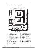
Страница 8: ... Header USB45 Blue 27 Internal Audio Connector AUX1 White 13 Chassis Fan Connector CHA_FAN1 28 LAN PHY 14 System Panel Connector PANEL1 29 ATX Power Connector ATXPWR1 15 Floppy Connector FLOPPY1 GE PRO HT DDR DIMM1 64 72 bit 184 pin module DDR DIMM2 64 72 bit 184 pin module IDE2 IDE1 FLOPPY1 AMR1 1 COM1 USB45 1 IR1 1 SPEAKER1 1 CHA_FAN1 SiS 962L CMOS Battery PCI 2 PCI 1 Super I O 2MB BIOS 1 AUDIO1...

Страница 9: ...eader USB45 Blue 27 Internal Audio Connector AUX1 White 13 Chassis Fan Connector CHA_FAN1 28 LAN PHY 14 System Panel Connector PANEL1 29 ATX Power Connector ATXPWR1 15 Floppy Connector FLOPPY1 GE PRO M2 DDR DIMM1 64 72 bit 184 pin module DDR DIMM2 64 72 bit 184 pin module IDE1 FLOPPY1 AMR1 1 COM1 USB45 1 IR1 1 SPEAKER1 1 CHA_FAN1 SiS 962L CMOS Battery PCI 2 PCI 1 Super I O 2MB BIOS 1 AUDIO1 JR1 JL...

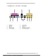
Страница 10: ...E Pro M2 1 Parallel Port 6 Line Out Lime 2 RJ 45 Port 7 USB 2 0 Ports 3 Game Port 8 VGA Port 4 Microphone Pink 9 PS 2 Keyboard Port Purple 5 Line In Light Blue 10 PS 2 Mouse Port Green This Manual http www manuallib com file 2630978 ...

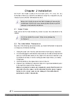
Страница 11: ...s before you install motherboard components or change any motherboard settings 1 Unplug the power cord from the wall socket before touching any component 2 To avoid damaging the motherboard components due to static electricity NEVER place your motherboard directly on the carpet or the like Also remember to use a grounded wrist strap or touch a safety grounded object before you handle components 3 ...

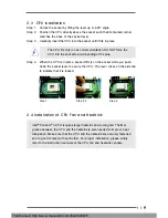
Страница 12: ...e press it firmly on the socket while you push down the socket lever to secure the CPU The lever clicks on the side tab to indicate that it is locked Step 1 Step 2 3 Step 4 2 4 Installation of CPU Fan and Heatsink Intel Pentium 4 CPU requires larger heatsink and cooling fan Thermal grease between the CPU and the heatsink is also needed to improve heat dissipation Make sure that the CPU and the hea...

Страница 13: ... have the 32 bit PCI interface AMR slot The AMR slot is used to insert an ASRock MR card optional with v 92 Modem functionality AGP slot The AGP slot is AGP 2 0 compliant and supports a 4X 2X 1X AGP card The ASRock AGP slot has a special locking mechanism which can securely fasten the inserted graphics card Installing an expansion card Step 1 Before installing the expansion card read the documenta...

Страница 14: ...in back panel and front panel at the same time 1 If the jumpers JL1 and JR1 are short see fig 1 both front panel and rear panel audio connectors can work 2 If both jumper caps on JL1 and JR1 are removed see fig 2 only front panel audio works However it requires your front panel to support the function Clear CMOS CLRCMOS1 see p 7 p 8 item 16 Note CLRCMOS1 allows you to clear the data in CMOS The da...

Страница 15: ...r hard disk drive to the primary IDE connector IDE1 blue and CD ROM to the secondary IDE connector IDE2 black USB 2 0 header ASRock I OTM provides 4 9 pin USB45 default USB 2 0 ports If those see p 7 p 8 item 12 USB 2 0 ports on the rear panel are not sufficient this USB 2 0 header is available to support 2 additional USB 2 0 ports Infrared module connector This connector supports an 5 pin IR1 opt...

Страница 16: ...er connector This connector allows you 4 pin SPEAKER 1 to attach to an external see p 7 p 8 item 17 speaker Chassis fan connector Connect the fan cable to the 3 pin CHA_FAN1 connector matching the black see p 7 p 8 item 13 wire to the ground pin CPU fan connector Connect the fan cable to the 3 pin CPU_FAN1 connector matching the black see p 7 p 8 item 4 wire to the ground pin ATX power connector C...

Страница 17: ...s and select among the predetermined choices Because the BIOS software is constantly being updated the following BIOS setup screens and descriptions are for reference purpose only and may not exactly match what you see on your screen 3 1 1 BIOS Menu Bar The top of the screen has a menu bar with the following selections MAIN Sets up the basic system configuration ADVANCED Sets up the advanced featu...

Страница 18: ... between the Month Day and Year fields System Time Hour Minute Second Set the system to the time that you specify Use keys to move between the Hour Minute and Second fields Floppy Drives Use this to set the type of floppy drives installed IDE Devices Use this to configure IDE devices AMIBIOS SETUP UTILITY VERSION 3 31a Main Advanced Security Power Boot Exit System Date System Time Floppy Drives ID...

Страница 19: ...tection fails it may due to that the hard disk is too old or too new If the hard disk was already formatted on an older system the BIOS Setup may detect incorrect parameters In these cases select User to manually enter the IDE hard disk drive parameters After entering the hard disk information into BIOS use a disk utility such as FDISK to partition and format new IDE hard disk drives This is neces...

Страница 20: ...he BIOS based on the drive information you entered LBA Mode This allows user to select the LBA mode for a hard disk 512 MB under DOS and Windows for Netware and UNIX user select Off to disable the LBA mode Block Mode Set the block mode to On will enhance hard disk performance by reading or writing more data during each transfer Fast Programmed I O Modes This allows user to set the PIO mode to enha...

Страница 21: ...from the BIN folder in the Support CD to display the menus 4 2 2 Drivers Menu The Drivers Menu shows the available devices drivers if the system detects installed devices Please install the necessary drivers to activate the devices 4 2 3 Utilities Menu The Utilities Menu shows the applications software that the motherboard supports Click on a specific item then follow the installation wizard to in...

Страница 22: ...e this feature it requires a computer system with an Intel Pentium 4 processor that supports Hyper Threading technology and an operating system that includes optimization for this technology such as Microsoft Windows XP Set to Auto if using Microsoft Windows XP or Linux kernel version 2 4 18 or higher This option will be hidden if the current CPU does not support Hyper Threading technology AMIBIOS...

Страница 23: ...ble or disable the use of USB controller USB Device Legacy Support Use this to enable or disable support to emulate legacy I O devices such as mouse keyboard etc DRAM CAS Latency This parameter controls the latency between the read command and the time the data available AMIBIOS SETUP UTILITY VERSION 3 31a Advanced AGP Aperture Size Onboard VGA Share Memory USB Controller USB Device Legacy Support...

Страница 24: ...oard FDC OnBoard Serial Port OnBoard Infrared Port OnBoard Parallel Port Parallel Port Mode EPP Version Parallel Port IRQ Parallel Port DMA Channel OnBoard Midi Port Midi IRQ Select OnBoard Game Port OnBoard IDE OnBoard LAN OnBoard AC 97 Audio OnBoard MC 97 Modem Setup Help F1 Help Esc Previous Menu F9 Setup Defaults F10 Save Exit Change Values Enter Select Sub Menu Select Item Peripheral Configur...

Страница 25: ... IDE channels by selecting Both Set to Disabled will disable the both Configuration options Disabled Primary Secondary Both OnBoard LAN This allows you to enable or disable the OnBoard LAN feature OnBoard AC 97 Audio Select Disabled Auto or Enabled for the onboard AC 97 Audio feature OnBoard MC 97 Modem Select Auto or Disabled for the onboard MC 97 Modem feature System Hardware Monitor You can che...

Страница 26: ...6 alphanumeric characters combination If you already have a password you must enter your current password first in order to create a new password Password Check Select the check point for Password Check Configuration options Setup Always If Setup option is selected the Password Check is performed before BIOS setup If Always option is selected the Password Check is performed before both boot up and...

Страница 27: ... PCI devices to turn on the system from the power soft off mode PS 2 Keyboard Power On Use this to enable or disable PS 2 keyboard to turn on the system from the power soft off mode RTC Alarm Power On Use this to enable or disable RTC Real Time Clock to power on the system If Enable is selected you must fill the RTC Alarm Date Hour Minute Second sub fields with the actual wake up time you desire A...

Страница 28: ...up to OS 2 operating system Boot Device Priority This allows you to set the boot device priority AMIBIOS SETUP UTILITY VERSION 3 31a Main Advanced Security Power Boot Exit Quick Boot Mode Boot Up Num Lock Boot To OS 2 Boot Device Priority Setup Help On No Enter to enable or disable the quick boot mode F1 Help Esc Exit F9 Setup Defaults F10 Save Exit Change Values Enter Select Sub Menu Select Item ...

Страница 29: ...efault settings will appear If you press Enter it will load the default values for all the setup configuration Discard Changes After you enter the sub menu the message Load setup original values will appear If you press ENTER original values will be restored and all changes are discarded AMIBIOS SETUP UTILITY VERSION 3 31a Main Advanced Security Power Boot Exit Exit Saving Changes Exit Discarding ...

Отзывы: