background image

2 4

2 4

2 4

2 4

2 4

2.10

2.10

2.10

2.10

2.10 Serial A

Serial A

Serial A

Serial A

Serial ATTTTTA (SA

A (SA

A (SA

A (SA

A (SATTTTTA) / Serial A

A) / Serial A

A) / Serial A

A) / Serial A

A) / Serial ATTTTTAII (SA

AII (SA

AII (SA

AII (SA

AII (SATTTTTAII) Hard Disks

AII) Hard Disks

AII) Hard Disks

AII) Hard Disks

AII) Hard Disks

Installation

Installation

Installation

Installation

Installation

This motherboard adopts NVIDIA

®

 GeForce 6150SE / nForce 430 chipset that

supports Serial ATA (SATA) / Serial ATAII (SATAII) hard disks and RAID functions. You
may install SATA / SATAII hard disks on this motherboard for internal storage devices.
This section will guide you to install the SATA / SATAII hard disks.

STEP 1: Install the SATA / SATAII hard disks into the drive bays of your chassis.
STEP 2: Connect the SATA power cable to the SATA / SATAII hard disk.
STEP 3: Connect one end of the SATA data cable to the motherboard’s SATAII

connector.

STEP 4: Connect the other end of the SATA data cable to the SATA / SATAII hard

disk.

2.11

2.11

2.11

2.11

2.11 Hot Plug and Hot Swap F

Hot Plug and Hot Swap F

Hot Plug and Hot Swap F

Hot Plug and Hot Swap F

Hot Plug and Hot Swap Functions for SA

unctions for SA

unctions for SA

unctions for SA

unctions for SATTTTTA / SA

A / SA

A / SA

A / SA

A / SATTTTTAII

AII

AII

AII

AII

HDDs

HDDs

HDDs

HDDs

HDDs

This motherboard supports Hot Plug  and Hot Swap functions for SATA / SATAII
Devices.

NOTE

What is Hot Plug Function?

If the SATA / SATAII HDDs are NOT set for RAID configuration, it is
called “Hot Plug” for the action to insert and remove the SATA / SATAII
HDDs while the system is still power-on and in working condition.
However, please note that it cannot perform Hot Plug if the OS has
been installed into the SATA / SATAII HDD.

What is Hot Swap Function?

If SATA / SATAII HDDs are built as RAID1 or RAID 5 then it is called
“Hot Swap” for the action to insert and remove the SATA / SATAII
HDDs while the system is still power-on and in working condition.
Содержание ALIVENF6P-VSTA

Страница 1: ...1 1 1 1 1 ALiveNF6P VSTA User Manual Version 1 1 PublishedNovember 2007 Copyright 2007 ASRock INC All rights reserved ...

Страница 2: ... or implied including but not limited to the implied warran ties or conditions of merchantability or fitness for a particular purpose In no event shall ASRock its directors officers employees or agents be liable for any indirect special incidental or consequential damages including damages for loss of profits loss of business loss of data interruption of business and the like even if ASRock has be...

Страница 3: ...I_SPDIF Header ConnectionGuide 22 2 9 SATAII Hard Disk Setup Guide 23 2 10 Serial ATA SATA Serial ATAII SATAII Hard Disks Installation 24 2 11 Hot Plug and Hot Swap Functions for SATA SATAII HDDs 24 2 12 SATA SATAII HDD Hot Plug Feature and Operation Guide 25 2 13 Driver InstallationGuide 27 2 14 Installing Windows 2000 XP XP 64 bit VistaTM VistaTM 64 bit Without RAID Functions 27 2 15 Installing ...

Страница 4: ... 4 Hardware Health Event Monitoring Screen 44 3 5 Boot Screen 45 3 5 1 Boot Settings Configuration 45 3 6 Security Screen 46 3 7 Exit Screen 47 4 4 4 4 4 Software Support Software Support Software Support Software Support Software Support 48 48 48 48 48 4 1 Install Operating System 48 4 2 Support CD Information 48 4 2 1 Running Support CD 48 4 2 2 DriversMenu 48 4 2 3 Utilities Menu 48 4 2 4 Conta...

Страница 5: ...of this manual occur the updated version will be available on ASRock website without further notice You may find the latest VGA cards and CPU support lists on ASRock website as well ASRock website http www asrock com If you require technical support related to this motherboard please visit our website for specific information about the model you are using www asrock com support index asp 1 1 1 1 1...

Страница 6: ...ty 4GB see CAUTION 4 Hybrid Booster CPU Frequency Stepless Control see CAUTION 5 ASRock U COP see CAUTION 6 Boot Failure Guard B F G ASRock AM2 Boost ASRock Patented Technology to boost memory performance up to 12 5 see CAUTION 7 Expansion Slot 1 x PCI Express x16 slot 1 x PCI Express x1 slot 2 x PCI slots Graphics Integrated NVIDIA GeForce6 class graphics DX9 0 VGA Pixel Shader 3 0 Max shared mem...

Страница 7: ... SMBIOS 2 3 1 Support Support CD Drivers Utilities AntiVirus Software Trial Version Hardware CPU Temperature Sensing Monitor Chassis Temperature Sensing CPU Fan Tachometer Chassis Fan Tachometer CPU Quiet Fan Voltage Monitoring 12V 5V 3 3V Vcore OS Microsoft Windows 2000 XP XP Media Center XP 64 bit VistaTM VistaTM 64 bit compliant Certifications FCC CE Microsoft WHQL Certificated WARNING Please r...

Страница 8: ...rboard functions properly and unplug the power cord then plug it back again To improve heat dissipation remember to spray thermal grease between the CPU and the heatsink when you install the PC system 7 This motherboard supports ASRock AM2 Boost overclocking technology If you enable this function in the BIOS setup the memory performance will improve up to 12 5 but the effect still depends on the A...

Страница 9: ...r minimum hardware requirements CPU Sempron 2800 Memory 512MB x 2 Dual Channel Premium 512MB Single Channel Basic 256MB x 2 Dual Channel Basic VGA DX9 0 with WDDM Driver If you use onboard VGA with total system memory size 512MB and plan to submit Windows VistaTM Basic logo please adjust the shared memory size of onboard VGA to 64MB If you use onboard VGA with total system memory size above 512MB ...

Страница 10: ... 4cm 9 6 in WIFI E 1 4Mb BIOS 6 7 1 2 4 3 5 8 9 10 11 12 13 14 15 16 17 18 19 20 21 22 23 24 25 26 27 28 1 PS2_USB_PW1 Jumper 15 System Panel Header PANEL1 2 ATX 12V Power Connector ATX12V1 16 USB 2 0 Header USB6_7 Blue 3 Chassis Fan Connector CHA_FAN1 17 Clear CMOS Jumper CLRCMOS1 4 AM2 940 Pin CPU Socket 18 Floppy Connector FLOPPY1 5 CPU Heatsink Retention Module 19 HDMI_SPDIF Header HDMI_SPDIF1...

Страница 11: ...eps for the software setting of Multi Streaming For Windows XP After restarting your computer you will find Mixer tool on your system Please select Mixer ToolBox click Enable playback multi streaming and click ok Choose 2CH or 4CH and then you are allowed to select Realtek HDA Primary output to use Rear Speaker and Front Speaker or select Realtek HDA Audio 2nd output to use front panel audio Then ...

Страница 12: ...r is switched off or the power cord is detached from the power supply Failure to do so may cause severe damage to the motherboard peripherals and or components 1 Unplug the power cord from the wall socket before touching any component 2 To avoid damaging the motherboard components due to static electricity NEVER place your motherboard directly on the carpet or the like Also remember to use a groun...

Страница 13: ...2 2 2 2 Installation of CPU Fan and Heatsink Installation of CPU Fan and Heatsink Installation of CPU Fan and Heatsink Installation of CPU Fan and Heatsink Installation of CPU Fan and Heatsink After you install the CPU into this motherboard it is necessary to install a larger heatsink and cooling fan to dissipate heat You also need to spray thermal grease between the CPU and the heatsink to improv...

Страница 14: ...e this motherboard and DIMM may be damaged 2 If you install only one memory module or two non identical memory modules it is unable to activate the Dual Channel Memory Technology Installing a DIMM Installing a DIMM Installing a DIMM Installing a DIMM Installing a DIMM Please make sure to disconnect power supply before adding or removing DIMMs or the system components Step 1 Unlock a DIMM slot by p...

Страница 15: ...x16 slot is used for PCI Express cards with x16 lane width graphics cards Installing an expansion card Installing an expansion card Installing an expansion card Installing an expansion card Installing an expansion card Step 1 Before installing the expansion card please make sure that the power supply is switched off or the power cord is unplugged Please read the documentation of the expansion card...

Страница 16: ... will disable onboard VGA D Sub function when the add on VGA card is inserted to this motherboard 4 Install the onboard VGA driver to your system If you have installed the onboard VGA driver already there is no need to install it again 5 Set up a multi monitor display For Windows 2000 XP XP 64 bit OS Right click the desktop choose Properties and select the Settings tab so that you can adjust the p...

Страница 17: ... date time and system setup parameters To clear and reset the system parameters to default setup please turn off the computer and unplug the power cord from the power supply After waiting for 15 seconds use a jumper cap to short pin2 and pin3 on CLRCMOS1 for 5 seconds However please do not clear the CMOS right after you update the BIOS If you need to clear the CMOS when you just finish updating th...

Страница 18: ...onnectors These four SerialATAII SATAII SATAII_1 PORT0 see p 10 No 11 connectors support SATAII SATAII_2 PORT1 see p 10 No 12 or SATA hard disk for internal SATAII_3 PORT2 see p 10 No 13 storage devices The current SATAII_4 PORT3 see p 10 No 14 SATAII interface allows up to 3 0 Gb s data transfer rate connect the black end to the IDE devices connect the blue end to the motherboard IDE1 PIN1 80 con...

Страница 19: ...1 see p 10 No 23 from sound sources such as a CD ROM DVD ROM TV tuner card or MPEG card Front Panel Audio Header This is an interface for the front 9 pin HD_AUDIO1 panel audio cable that allows see p 10 No 24 convenient connection and control of audio devices USB_PWR USB_PWR P 7 P 7 P 6 P 6 GND GND DUMMY 1 J_SENSE OUT2_L 1 MIC_RET PRESENCE GND OUT2_R MIC2_R MIC2_L OUT_RET CD L GND GND CD R CD1 1 I...

Страница 20: ...thout the fan speed control function If you plan to connect the 3 Pin CPU fan to the CPU fan connector on this motherboard please connect it to Pin 1 3 3 Pin Fan Installation Pin 1 3 Connected GND 12V CHA_FAN_SPEED 4 3 2 1 GND 12V CPU_FAN_SPEED FAN_SPEED_CONTROL D MIC_RET and OUT_RET are for HD audio panel only You don t need to connect them for AC 97 audio panel E Enter BIOS Setup Utility Enter A...

Страница 21: ... white end B or C of HDMI_SPDIF cable to the HDMI_SPDIF connector of HDMI VGA card A black end B white end 2 pin C white end 3 pin ATX 12V Power Connector Please note that it is necessary 4 pin ATX12V1 to connect a power supply with see p 10 No 2 ATX 12V plug to this connector Failing to do so will cause power up failure ATX Power Connector Please connect anATX power 24 pin ATXPWR1 supply to this ...

Страница 22: ...er to the user manual of HDMI VGA card vendor Incorrect connection may cause permanent damage to this motherboard and the HDMI VGA card white end 2 pin B white end 3 pin C Please do not connect the white end of HDMI_SPDIF cable to the wrong connector of HDMI VGA card or other VGA card Otherwise the motherboard and the VGA card may be damaged For example this picture shows the wrong example of conn...

Страница 23: ...may fail to run at SATAII mode Western Digital If pin 5 and pin 6 are shorted SATA 1 5Gb s will be enabled On the other hand if you want to enable SATAII 3 0Gb s please remove the jumpers from pin 5 and pin 6 SAMSUNG If pin 3 and pin 4 are shorted SATA 1 5Gb s will be enabled On the other hand if you want to enable SATAII 3 0Gb s please remove the jumpers from pin 3 and pin 4 HITACHI Please use th...

Страница 24: ... the motherboard s SATAII connector STEP4 Connect the other end of the SATA data cable to the SATA SATAII hard disk 2 11 2 11 2 11 2 11 2 11 Hot Plug and Hot Swap F Hot Plug and Hot Swap F Hot Plug and Hot Swap F Hot Plug and Hot Swap F Hot Plug and Hot Swap Functions for SA unctions for SA unctions for SA unctions for SA unctions for SAT T T T TA SA A SA A SA A SA A SAT T T T TAII AII AII AII AII...

Страница 25: ...ocess the SATA SATAII HDDHot Plug please check below cable accessories from the motherboard gift box pack A 7 pin SATA data cable B SATA power cable with SATA 15 pin power connector interface The SATA 15 pin power connector Black connect to SATA SATAII HDD Points of attention before you process the Hot Plug 1 Below operation procedure is designed only for our motherboard which supports SATA SATAII...

Страница 26: ... Connect SATA data cable to the SATA SATAII HDD How to Hot Unplug a SATA SATAII HDD Points of attention before you process the Hot Unplug Please do follow below instruction sequence to process the Hot Unplug improper procedure will cause the SATA SATAII HDD damage and data loss Please connect SATA power cable 1x4 pin end White to the power supply 1x4 pin cable Step 1 Step 2 Step 3 Step 4 Step 2 SA...

Страница 27: ...ow below procedures according to the OS you install Before installing Windows 2000 to your system your Windows 2000 optical disk is supposed to include SP4 If there is no SP4 included in your disk please visit the below website for proper procedures of making a SP4 disk http www microsoft com Windows2000 downloads servicepacks sp4 spdeploy htm the_integrated_installation_fmay 2 13 2 13 2 13 2 13 2...

Страница 28: ...en you will see these messages Please insert a blank formatted diskette into floppy drive A press any key to start Please insert a floppy diskette into the floppy drive and press any key E The system will start to format the floppy diskette and copy SATA SATAII drivers into the floppy diskette STEP 2 Set Up BIOS A Enter BIOS SETUP UTILITY Advanced screen IDE Configuration B Set the SATA Operation ...

Страница 29: ...RAID configuration by using the Windows RAID installation guide in the following path in the Support CD RAID Installation Guide STEP 2 Use RAID Installation Guide to set RAID configuration Before you start to configure RAID function you need to check the RAID installation guide in the Support CD for proper configuration Please refer to the BIOS RAID installation guide part of the document in the f...

Страница 30: ...tton on the system chassis You may also restart by turning the system off and then back on Because the BIOS software is constantly being updated the following BIOS setup screens and descriptions are for reference purpose only and they may not exactly match what you see on your screen 3 1 1 3 1 1 3 1 1 3 1 1 3 1 1 BIOS Menu Bar BIOS Menu Bar BIOS Menu Bar BIOS Menu Bar BIOS Menu Bar The top of the ...

Страница 31: ...tem Time Hour Minute Second Use this item to specify the system time System Date Day Month Date Year Use this item to specify the system date 3 1 2 3 1 2 3 1 2 3 1 2 3 1 2 Navigation Keys Navigation Keys Navigation Keys Navigation Keys Navigation Keys Please check the following table for the function description of each navigation key Navigation Key s Function Description Moves cursor left or righ...

Страница 32: ...onfiguration Chipset Configuration ACPI Configuration IDE Configuration PCIPnP Configuration Floppy Configuration SuperIO USB Configuration Configuration 3 3 3 3 3 3 3 3 3 3 Advanced Screen Advanced Screen Advanced Screen Advanced Screen Advanced Screen In this section you may set the configurations for the following items CPU Configuration Chipset Configuration ACPI Configuration IDE Configuratio...

Страница 33: ...onfiguration CPU Configuration AM2 Boost If you set this option to Enabled you will enable ASRock AM2 Boost function which will improve the memory performance The default value is Disabled Please refer to caution 7 on page 8 for details Overclock Mode Use this to select Overclock Mode The default value is Auto Configura tion options Auto CPU PCIE Sync and CPU PCIE Async CPU Frequency MHz Use this ...

Страница 34: ...item Processor Voltage This item will show when Multiplier Voltage Change is set to Manual otherwise it will be hidden The range of the value depends on the CPU you adopt on this motherboard However for safety and system stability it is not recommended to adjust the value of this item reduce CPU voltage and memory frequency and lead to system stability or compatibility issue with some memory modul...

Страница 35: ... is Auto TRTP Use this to adjust TRTP values Configuration options Auto 2 4CLK and 3 5CLK The default value is Auto TRAS Use this to adjust TRAS values Configuration options Auto 5CLK to 18CLK The default value is Auto TRRD Use this to adjust TRRD values Configuration options Auto 2CLK 3CLK 4CLK and 5CLK The default value is Auto TRC Use this to adjust TRC values Configuration options 11CLK to 26C...

Страница 36: ...ust TRWTTD values Configuration options Auto 2CLK 3CLK 4CLK and 5CLK The default value is Auto MA Timing Use this to adjust values for MA timing Configuration options Auto 2T 1T The default value is Auto Bank Interleaving Interleaving allows memory accesses to be spread out over banks on the same node or accross nodes decreasing access contention ...

Страница 37: ...el Select Auto Enabled or Disabled for the onboard HDAudio Front Panel Share Memory This allows you to set share memory feature The default value is Auto Configuration options Auto 16MB 32MB 64MB 128MB and 256MB Primary Graphics Adapter This item will switch the PCI Bus scanning order while searching for video card It allows you to select the type of Primary VGA in case of multiple video controlle...

Страница 38: ...he function Repost Video on STR Resume will be hidden Repost Video on STR Resume This feature allows you to repost video on STR resume STR refers to suspend to RAM Away Mode Support Use this item to enable or disable Away Mode support under Windows XP Media Center OS The default value is Disabled Restore on AC Power Loss This allows you to set the power state after an unexpected AC power loss If P...

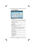
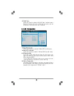
Страница 39: ...ion to Enabled if you plan to use this motherboard to submit Windows VistaTM certification 3 3 4 3 3 4 3 3 4 3 3 4 3 3 4 IDE Configuration IDE Configuration IDE Configuration IDE Configuration IDE Configuration OnBoard IDE Controller Use this item to enable or disable the OnBoard IDE Controller feature OnBoard SATA Controller Use this item to enable or disable the OnBoard SATA Controller feature S...

Страница 40: ...user select Disabled to disable the LBA Large mode Block Multi Sector Transfer The default value of this item is Auto If this feature is enabled it will enhance hard disk performance by reading or writing more data during each transfer PIO Mode Use this item to set the PIO mode to enhance hard disk performance by optimizing the hard disk timing DMA Mode DMA capability allows the improved transfer ...

Страница 41: ...ting Technology feature Configuration options Disabled Auto Enabled 32Bit Data Transfer Use this item to enable 32 bit access to maximize the IDE hard disk data transfer rate 3 3 5 3 3 5 3 3 5 3 3 5 3 3 5 PCIPnP Configuration PCIPnP Configuration PCIPnP Configuration PCIPnP Configuration PCIPnP Configuration Setting wrong values in this section may cause the system to malfunction PCI Latency Timer...

Страница 42: ...l Port IRQ Enabled 3F8 IRQ4 Disabled 378 ECP EPP 1 9 DMA3 IRQ7 3 3 6 3 3 6 3 3 6 3 3 6 3 3 6 Floppy Configuration Floppy Configuration Floppy Configuration Floppy Configuration Floppy Configuration In this section you may configure the type of your floppy drive 3 3 7 3 3 7 3 3 7 3 3 7 3 3 7 Super IO Configuration Super IO Configuration Super IO Configuration Super IO Configuration Super IO Configu...

Страница 43: ...lel port The default value is ECP EPP If this option is set to ECP EPP it will show the EPP version in the following item EPP Version Configuration options Normal Bi Directional and ECP EPP EPP Version Use this item to set the EPP version Configuration options 1 9 and 1 7 ECP Mode DMA Channel Use this item to set the ECP mode DMA channel Configuration options DMA0 DMA1 and DMA3 Parallel Port IRQ U...

Страница 44: ...ect Auto so that the system will start to auto detect if there is no USB device connected Auto option will disable the legacy USB support 3 4 3 4 3 4 3 4 3 4 Hardware Health Event Monitoring Screen Hardware Health Event Monitoring Screen Hardware Health Event Monitoring Screen Hardware Health Event Monitoring Screen Hardware Health Event Monitoring Screen In this section it allows you to monitor t...

Страница 45: ...eature Select Screen Select Item Change Option F1 General Help F9 Load Defaults F10 Save and Exit ESC Exit v02 54 C Copyright 1985 2003 American Megatrends Inc Boot Boot From Onboard LAN Bootup Num Lock Disabled On 3 5 3 5 3 5 3 5 3 5 Boot Screen Boot Screen Boot Screen Boot Screen Boot Screen In this section it will display the available devices on your system for you to config ure the boot setti...

Страница 46: ...er password you may also clear it BIOS SETUP UTILITY Main Advanced H W Monitor Boot Exit Install or Change the password Select Screen Select Item Enter Change F1 General Help F10 Save and Exit ESC Exit F9 Load Defaults v02 54 C Copyright 1985 2003 American Megatrends Inc Security Change Supervisor Password Change User Password Security Settings Supervisor Password Not Installed User Password Not I...

Страница 47: ...een Save Changes and Exit When you select this option it will pop out the following message Save configuration changes and exit setup Select OK to save the changes and exit the BIOS SETUP UTILITY Discard Changes and Exit When you select this option it will pop out the following message Dis card changes and exit setup Select OK to exit the BIOS SETUP UTILITY without saving any changes Discard Chang...

Страница 48: ... 1 Running The Support CD To begin using the support CD insert the CD into your CD ROM drive The CD automatically displays the Main Menu if AUTORUN is enabled in your computer If the Main Menu did not appear automatically locate and double click on the file ASSETUP EXE from the BIN folder in the Support CD to display the menus 4 2 2 Drivers Menu 4 2 2 Drivers Menu 4 2 2 Drivers Menu 4 2 2 Drivers ...

Отзывы: