


2 9
2 9
2 9
2 9
2 9
1
I
R
TX
+5V
SB
Hotplug#
I
RR
X
G
N
D
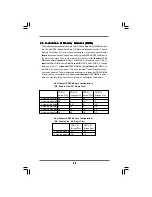
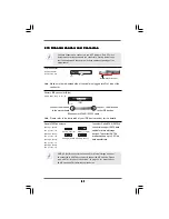
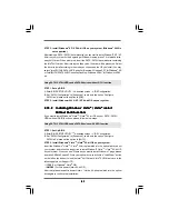
DeskExpress Hot Plug Detection
This header supports the Hot
Header
Plug detection function for
(5-pin IR1)
ASRock DeskExpress.
(see p.11 No. 24)
C
D
-L
G
N
D
G
N
D
C
D
-
R
CD1
J_SENSE
OUT
2
_L
1
MI
C
_RET
PRESEN
C
E#
GND
OUT
2
_R
MI
C2
_R
MI
C2
_L
OUT_RET
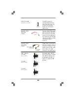
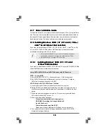
Internal Audio Connectors
This connector allows you
(4-pin CD1)
to receive stereo audio input
(CD1: see p.11 No. 28)
from sound sources such as
a CD-ROM, DVD-ROM, TV
tuner card, or MPEG card.
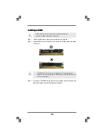
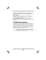
Front Panel Audio Header
This is an interface for front
(9-pin HD_AUDIO1)
panel audio cable that allows
(see p.11 No. 27)
convenient connection and
control of audio devices.
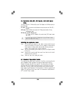
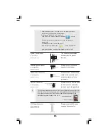
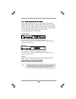
WiFi Header
This header supports WiFi+AP
(11-pin WIFI)
function with ASRock
(see p.11 No. 23)
WiFi-802.11g or WiFi-802.11n
module, an easy-to-use wireless
local area network (WLAN)
adapter. It allows you to create a
wireless environment and enjoy the
convenience of wireless network
connectivity.
1
USB
+5V_1
NC
NC
G
N
D
1
P
LT
RS
T#
+3
S
V
B
USB
+5V_1
D
0-
D
0+
G
N
D
1
P
ME#
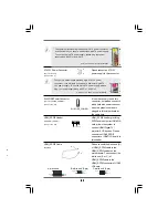
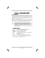
1. High Definition Audio supports Jack Sensing, but the panel wire on
the chassis must support HDA to function correctly. Please follow the
instruction in our manual and chassis manual to install your system.
2. If you use AC’97 audio panel, please install it to the front panel audio
header as below:
A. Connect Mic_IN (MIC) to MIC2_L.
B. Connect Audio_R (RIN) to OUT2_R and Audio_L (LIN) to OUT2_L.
C. Connect Ground (GND) to Ground (GND).
D. MIC_RET and OUT_RET are for HD audio panel only. You don’t
need to connect them for AC’97 audio panel.
E. Enter BIOS Setup Utility. Enter Advanced Settings, and then select
Chipset Configuration. Set the Front Panel Control option from
[Auto] to [Enabled].


