background image

22

English

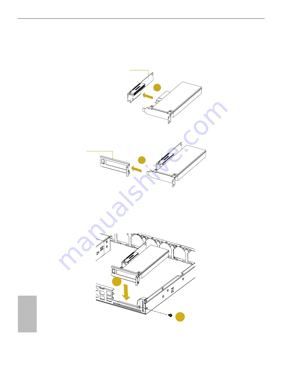
4.  Install the add-in card into the connector on the riser card.  

*You need to purchase a compatible riser card seperately if needed.

5.  Slide the add-in card attached to the riser card into the add-in card retainer plate.

4

5

Retainer Plate

Riser Card

6.  Lower the rear of the add-in card and align the card faceplate with the opening in the 

back of the system. Gently press the riser card into the motherboard connector until 

fully seated.

7.  Secure the add-in card to the chassis with the screw.

7

6

Содержание 1U12LX Series

Страница 1: ......

Страница 2: ...implied including but not limited to the implied warranties or conditions of merchantability or itness for a particular purpose In no event shall ASRockRack its directors oicers employees or agents b...

Страница 3: ...INCORRECT TYPE DISPOSE OF USED BATTERIES ACCORDING TO THE INSTRUCTIONS Important Safety Instructions Pay close attention to the following safety instructions before performing any of the operation Bas...

Страница 4: ...want to know more about ASRockRack you re welcome to visit ASRockRack s website at www ASRockRack com or you may contact your dealer for further information ASRockRack Incorporation 6F No 37 Sec 2 Jho...

Страница 5: ...em Front Panel 7 2 4 System Rear Panel 7 2 5 Front Control Panel Buttons and LEDs 8 Chapter 3 Hardware Installation and Maintenance 10 3 1 Server Top Cover 11 3 2 Hard Drive 13 3 3 Power Supply 19 3 4...

Страница 6: ...ire technical support related to this product please visit our website for speciic information about the model you are using ASRockRack s Website www ASRockRack com 2 he illustrations shown in this ma...

Страница 7: ...ation LED 1 x Hard drive activity LED 2 x Network activity LEDs 12 x HDD status LEDs 12 x HDD Fail LEDs I O Ports 2 x USB 2 0 ports Drive Bay Internal 12 x 3 5 SATA HDDs 6Gb s 2 x 2 5 SATA HDDs 6Gb s...

Страница 8: ...w his chapter provides diagrams showing the location of important components of the server system 2 1 System Components 2 x Power Supply Units 12 x 3 5 HDD Carriers 2 x 2 5 HDD Carriers 4 x System Fan...

Страница 9: ...4 English 2 2 Cable Connections 1 2 5 6 7 8 9 3 4 12 13 14 15 17 18 19 20 22 23 24 25 11 16 21 26 10...

Страница 10: ...cable 1 BPB power cable 12 3 5 HDD 0 BP1 N A 13 3 5 HDD 1 BP1 N A 14 3 5 HDD 2 BP1 N A 15 3 5 HDD 3 BP1 N A 16 HDD Backplane 2 BP2 SB PDB MiniSAS to SATA MiniSAS cable 2 BPB power cable 17 3 5 HDD 4 B...

Страница 11: ...arious server boards Please refer to the Quick Installation Guide to know the exact headers or cables to be connected on the server board you purchase For more detailed information about server board...

Страница 12: ...nel Buttons and LEDs 2 4 System Rear Panel 1 2 3 4 No Description 1 Power Supply Unit 2 I O Shield depends on the speciication of the server board 3 Rear Vent 4 1 x PCI Express Slot for the riser card...

Страница 13: ...type of the server board NMI Nonmaskable Interrupt Button Press the NMI button with a paper clip or pin to generate a nonmaskable interrupt and to put the server in a halt state for examination System...

Страница 14: ...ower of UID LED Status Description Blue System identiication is active Of System identiication is disabled HDD Activity LED Status Description Blinking Green HDD access Any of the HDDs is ccessing dat...

Страница 15: ...electricity may damage components Wear a grounded wrist strap if available Installing Procedures he followings are prerequisite to be installed 3 5 or 2 5 HDD s Power Supplies Pre installed Server Boa...

Страница 16: ...the top cover to the chassis 2 Push the top cover toward the rear of the chassis to remove the cover from the locked position 3 Lit up and remove the top cover 1 Before removing the top cover power of...

Страница 17: ...alling the Server Top Cover 3 3 3 3 3 3 2 1 1 Lower the top cover on the chassis making sure the side latches align with the cutouts 2 Slide the top cover toward the front 3 Secure the top cover with...

Страница 18: ...cables irst before installing any of the 3 5 HDDs Meanwhile please well organize your cables and be careful with your cable routing You can refer to the Quick Installation Guide for more information...

Страница 19: ...the hard drive using the four screws 3 Place the hard drive carrier on the base plate with the thumb screw facing the front of the chassis 4 Align the keyhole openings on the base with the locating pi...

Страница 20: ...ish Removing a Hard Disk Drive Base Plate from the Chassis Organize your cables and place them under the hard drive base plates before installing 3 5 HDDs 1 Remove the screws that secure the hard driv...

Страница 21: ...or a riser card to be in stalled in the system Before installing a 2 5 HDD make sure the riser card is removed 2 2 5 HDDs are not supported for C2500DI C2750DI motherboard Removing 2 5 Hard Drive Car...

Страница 22: ...e 2 5 HDDs into the carrier with the label facing down and the connector ends toward the front of the chassis Carefully align the mounting holes in the hard drive and the carrier 2 Secure the hard dri...

Страница 23: ...18 English 4 Place the drive carrier back to the chassis with screw holes aligned 5 Secure the drive carrier with screws 5 5 4...

Страница 24: ...d for operation with the second power supply purely as a redundant load sharing backup It can be removed without afecting system operation Installing and Removing the Power Supply 1 Align the power su...

Страница 25: ...U 1 Hold onto the power supply handle while pressing the locking lever towards the power supply handle 2 Pull to remove the power supply from the chassis 2 1 1 1 Before replacing the power supply powe...

Страница 26: ...card assembly from the chassis 3 Slide the add in card iller plate out sideways 1 You can install an add in card to the chassis only when you have a riser card to be installed on the server board 2 Be...

Страница 27: ...add in card attached to the riser card into the add in card retainer plate 4 5 Retainer Plate Riser Card 6 Lower the rear of the add in card and align the card faceplate with the opening in the back...

Страница 28: ...connecter and remove the failed fan 2 Align the mounting holes on the fan bar with the fan mounts on the replacement fan corners 3 Gently place the fan on the fan bar Make sure the fan is well seated...

Страница 29: ...kplanes 1 Remove all of cables connected to the backplanes 2 Loosen the securing screws on the backplanes 3 Lit the backplanes up from the chassis Hold the backplanes only by the edges Before removing...

Страница 30: ...3 Position the server board in the server system Align mounting holes of the server board to the standof on the chassis 4 Aix the screws clockwise into the mounting holes in all of the corners of the...

Страница 31: ...cables for your chassis system Cable type and quantity vary depending on the server board that comes with your system 1 MiniSAS to SATA Cable 1 490mm Quantity 1 Port 0 3 BP1 Server Board 2 MiniSAS to...

Страница 32: ...Cable 3 690mm Quantity 1 Port 8 11 BP3 Server Board 4 MiniSAS to MiniSAS Cable 1 220mm Quantity 1 Server Board BP1 5 MiniSAS to MiniSAS Cable 2 380mm Quantity 1 6 MiniSAS to MiniSAS Cable 3 560mm Qua...

Страница 33: ...Quantity 1 Server Board SATA HDD 8 SATA Cable 1 500mm Quantity 1 9 SMBus Cable 900mm Quantity 1 NC CQC Server Board BP1 BP2 BP3 10 Front Panel Cable 1000mm Quantity 1 FPB PANEL1 AUX_PANEL1 NMI_BTN Ser...

Страница 34: ...Remove all 3 5 HDDs carriers when you are going to connect various components with cables 2 Connections and cable routing may difer depending on various server boards Please refer to the Quick Install...

Страница 35: ...I_SAS1 SMB_1 SGPIO1 J2 CON1 CON2 CON3 CON4 No Description 1 I2C Address Settings J2 2 SGPIO Code Programming Pin SGPIO1 3 Debug Header J1 4 BMC SMBus Connector SMB_1 5 Mini SAS Connector MINI_SAS1 6 D...

Страница 36: ...nt AUX Panel 3 Front USB 2 0 Connector Front_USB_1 4 Front USB 2 0 Connector Front_USB_2 5 NMI Button CON2 6 System Reset Button CON1 7 LAN 1 Activity LED LED2 8 LAN 2 Activity LED LED3 9 HDD Activity...

Страница 37: ...4 2 1 5 6 1 PSU_SMB1 BPB_PWR1 ATX12V1 ATXPWR1 CON2 CON1 No Description 1 PMBus Connnector PSU_SMB1 2 BPB Power Connector BPB_PWR1 3 ATX 8pin Power Connector ATX12V1 4 ATX 24pin Power Connector ATXPWR...

Страница 38: ...s I2C Address Setting Jumper for BP 7 pin J2 see p 29 No 1 3 4 BP1 5 6 BP3 7 8 BP2 Pin Deinitions DC Power Connector PWR1 PWR2 see p 29 No 6 7 5V 12V GND1 GND2 he 4 pin connectors provide power to the...

Страница 39: ...R 1 he header supports two USB 2 0 ports on the front panel Front and Auxiliary Panel Header 17 pin FRONT AUX PANEL see p 30 No 2 PWR BTN PLED PLED HDLED 1 NMI BTN 3VSB LAN1 LED GND LAN2 LED HDLED LOC...

Страница 40: ...ATXPWR1 see p 31 No 2 12 7 6 1 his connector is used to connect BPB and the power connector on the power distribution board PMBus Connector 5 pin PSU_SMB1 see p 31 No 1 3V 1 GND PSU_ALT PSU_CLK PSU_DA...

Страница 41: ...e slide rail assemblies to the rack Slide Rail Chassis Rail Removing the Chassis Rail from the Slide Rail Assembly 1 Pull out the inner chassis rail from the rail assembly 2 Push the white chassis rai...

Страница 42: ...ail toward the front of the chassis until the chassis rail clips Make sure the rail is installed in the correct direction 3 Secure the chassis rail to the server chassis with screws 4 Repeat for the r...

Страница 43: ...three holes of free space above the slide rail bracket 2 For the rack with square mounting holes insert cage nuts in the holes that you will use on the rack 11U 12U 1 Free Space Cage Nuts 3 Extend the...

Страница 44: ...modate the depth of the rack 11U 11U 5 Align the holes on the brackets with the mounting holes you selected on the rack 6 Tighten the screws to secure the slide rails to the rack Make sure the rear br...

Страница 45: ...erly and securely attached to the rack 2 Fully extend the slide rails from the rack by pulling the inner rails out until they are locked and cannot be pulled out further 11U 12 U To slide an inner rai...

Страница 46: ...he server to the rack with screws 5 To remove the server from the rack reverse these instructions he server is heavy For safe liting two or more persons are required to install the server into the rac...

Страница 47: ...ish Optional Accessory Please purchase the following optional accessories seperately if needed Rail Assembly Kit Vendor Model Name SIN JHAO SJ 4095 32 T6 Riser Card Vendor Model Name ASRock Rack 1U12L...

Отзывы: