

EPC612D4I
Quick Installation Guide
www.asrockrack.com
9
LAN Port LED Indications
Activity / Link LED
Speed LED
Status
Description
Status
Description
Off
No Link
Off
10M bps connection or no
link
Blinking Yellow
Data Activity
Yellow
100M bps connection
On
Link
Green
1Gbps connection
ACT/LINK LED
SPEED LED
LAN Port
6
7
1
2
3
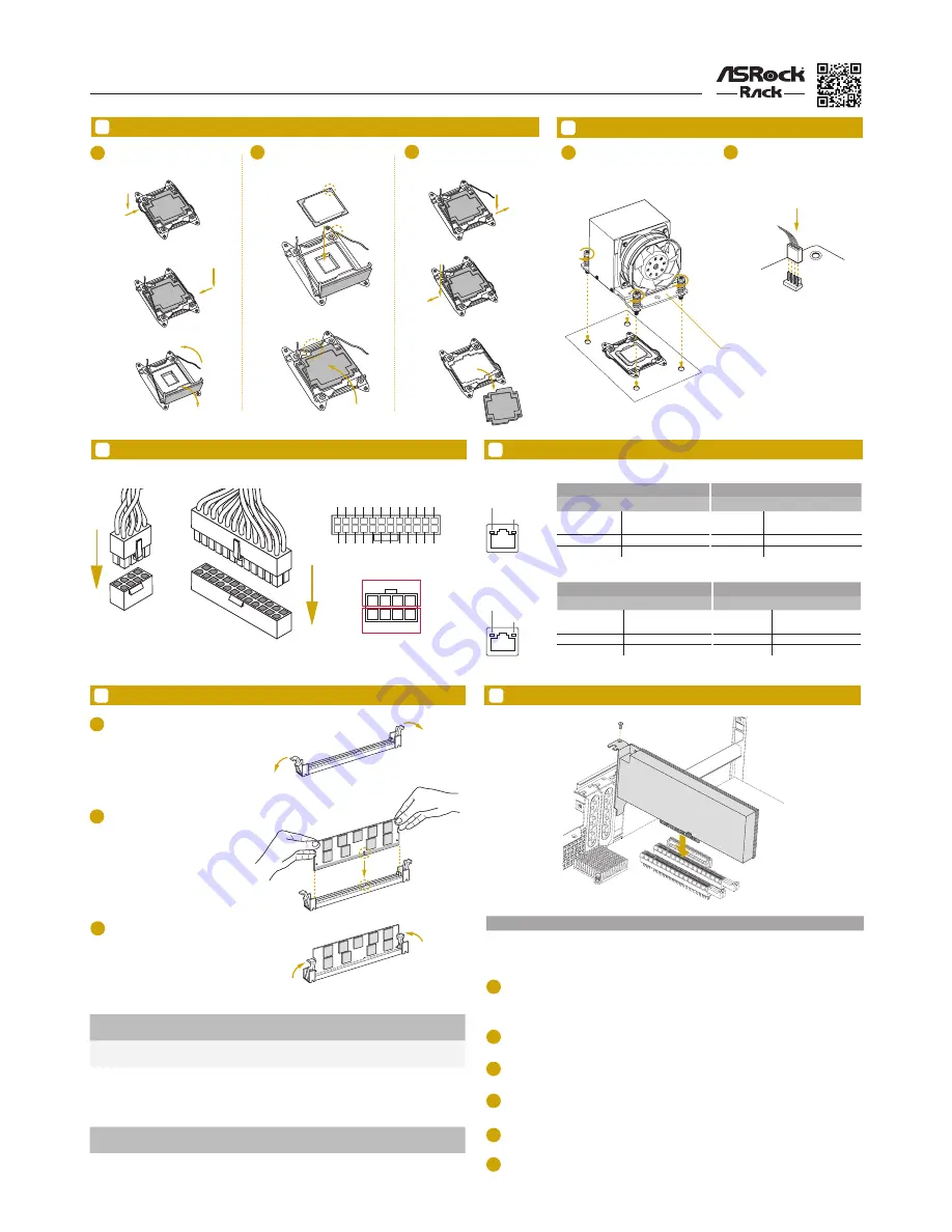
Open the socket levers and the
CPU socket cover.
Install the processor and close
the socket cover.
Close the socket levers. Remove
the CPU protection cap.
Install the CPU Fan and Heatsink
1
2
Apply the thermal grease. Install the
CPU fan and heatsink and secure
the screws.
Connect the CPU fan to the CPU
FAN connector.
11
Install the PCIE Card
1
Before installing an expansion card, please make sure that the power supply is switched off or the power
cord is unplugged. Please read the documentation of the expansion card and make necessary hardware
settings for the card before you start the installation.
2
Remove the system unit cover (if your motherboard is already installed in a chassis).
Remove the bracket facing the slot that you intend to use. Keep the screws for later use.
3
IPMI LAN Port
LAN Port
Install the Processor
CPU
_FA
N
A
B
A
B
A
B
A
B
B
A
ACT/LINK LED
SPEED LED
LAN Port
Activity / Link LED
Speed LED
Status
Description
Status
Description
Off
No Link
Off
10Mbps connection or
no link
Blinking Green
Data Activity
Yellow
100Mbps connection
On
Link
Green
1Gbps connection
10
Install the Memory
1
2
3
Unlock a DIMM slot by pressing
the module clips outward.
Insert the memory module.
Lock the clips.
8
Install the Power Cables
3V
3V
GN
D
GN
D
5V
5V
GN
D
PWROK_PS
5VSB
12
V
12
V
3V
12
1
13
24
3V
-12V
GN
D
PSON#
GN
D
GN
D
GN
D
5V
5V
5V
GN
D
N/
A
4
8
1
5
+12V2
GND
Dual Channel Memory Configuration
Priority
DDR4_A1
DDR4_B1
DDR4_C1
DDR4_D1
1
Populated
Populated
2
Populated
Populated
Populated
Populated
Quad Channel Memory Configuration
Priority
DDR4_A1
DDR4_B1
DDR4_C1
DDR4_D1
1
Populated
Populated
Populated
Populated
Align the card connector with the slot and press firmly until the card is completely seated on the slot.
Fasten the card to the chassis with screws.
Replace the system cover.
4
5
6
Slot
Generation
Mechanical
Electrical
Source
PCIE 7
3.0
x16
x16
CPU 1
CPU fan for narrow ILM socket
*Support an active or passive heatsink
We recommend using the CPU Installation tool to avoid CPU pin-bent problem.


