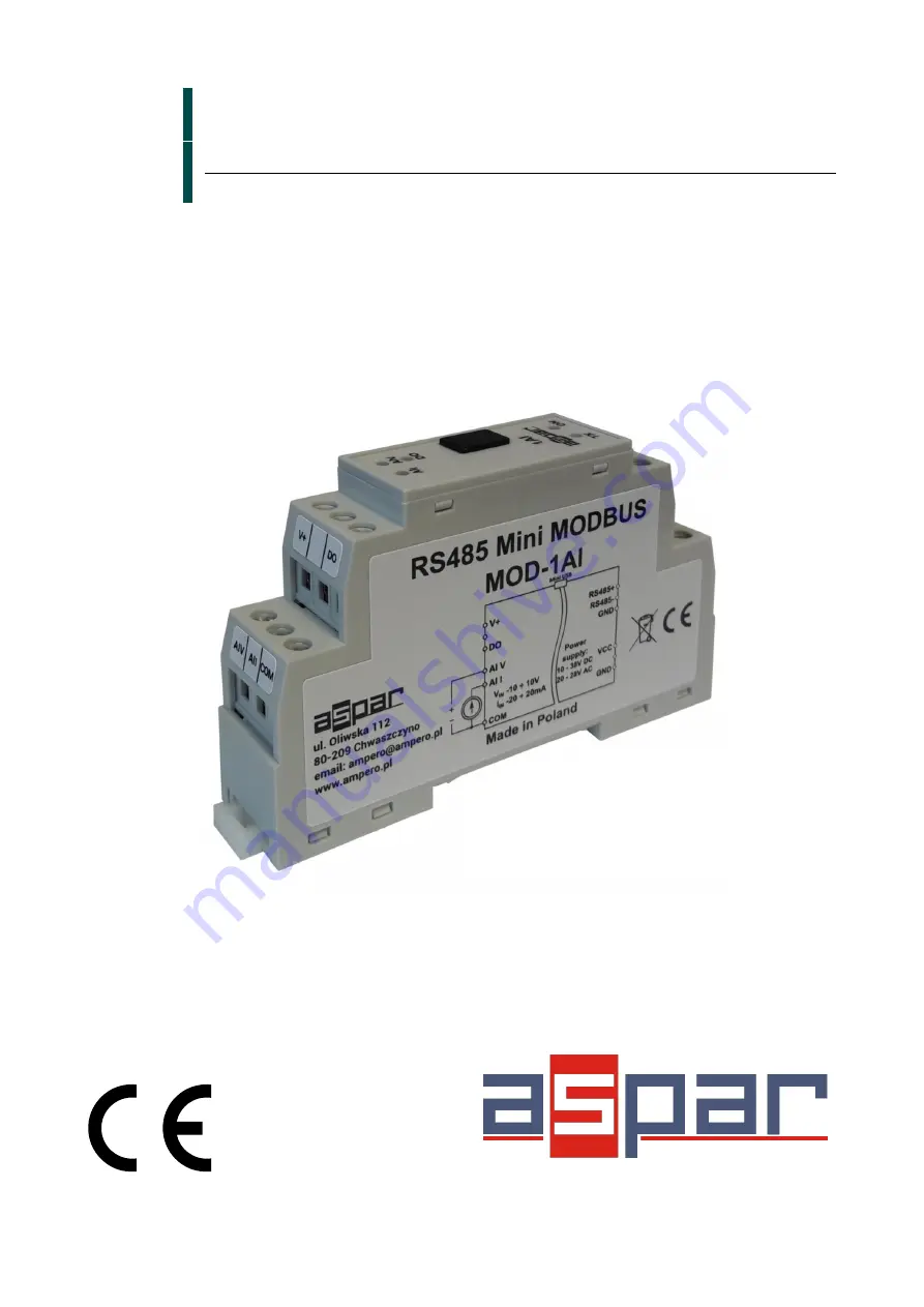
Mini Modbus 1AI
Expansion Module – 1 analog input, 1 digital output
Version 1.3
User Manual
Manufactured for
Страница 1: ...Mini Modbus 1AI Expansion Module 1 analog input 1 digital output Version 1 3 User Manual Manufactured for...
Страница 2: ...ncurring any liability for the purposes of commercial law This information does not release you from the obligation of own judgement and verification We reserve the right to change product specificati...
Страница 3: ...age measurement and 1 input for current measurement both inputs can be used in this same time In addition the module is equipped with 1 configurable digital output PNP or NPN type This module is conne...
Страница 4: ...processing time 70ms channel Voltage measurement error Max 1 7 Current measurement error Max 0 1 Digital outputs Maximum current and voltage 250mA 50V Temperature Work 20 C 65 C Storage 40 C 85 C Conn...
Страница 5: ...ould be taken at the installation stage to prevent these effects These protective steps include control cabinet grounding module grounding cable shield grounding protective elements for electromagneti...
Страница 6: ...3 30001 Input Registers Registered Read 3 4 40001 Output Registers Registered Read Write 4 6 16 3 4 Communication settings The data stored in the modules memory are in 16 bit registers Access to regi...
Страница 7: ...bit 2 two stop bits 40004 3 0x03 Data Bits MSB 7 7 data bits 8 8 data bits 40006 5 0x05 Response delay Time in ms 40007 6 0x06 Modbus Mode 0 RTU 1 ASCII 4 Indicators Indicator Description ON LED indi...
Страница 8: ...5 MODBUS Module 8AI User Manual 5 Block diagram 6 Module Connection Expansion Module 1 analog input 1 digital output User Manual Version 1 3 8 12 MUX ADC VIN IIN 100 COM V OUT C RS485 VCC GND GND 485...
Страница 9: ...igital output 30053 52 0x34 Voltage Read Voltage in V 30054 53 0x35 Current Read Current in A or 30055 54 0x36 Alarm max voltage Read Write Maximum value of voltage excess which causes set bit no 1 in...
Страница 10: ...arm hysteresis Read Write Hysteresis for alarm 7 2 Bit access Modbus Address Dec Address Hex Address Register name Access Description 801 800 0x320 Voltage input Read Voltage input state 802 801 0x321...
Страница 11: ...ent value of other registers of the module This program can be a convenient way to test the system as well as to observe real time changes in the registers Communication with the module is done via th...
Страница 12: ...5 3 3 Types of Modbus Registers 6 3 4 Communication settings 6 3 4 1 Default settings 6 3 4 2 Configuration registers 7 4 Indicators 7 5 Block diagram 8 6 Module Connection 8 7 Modules Registers 9 7...