EN 18
INSTALLATION
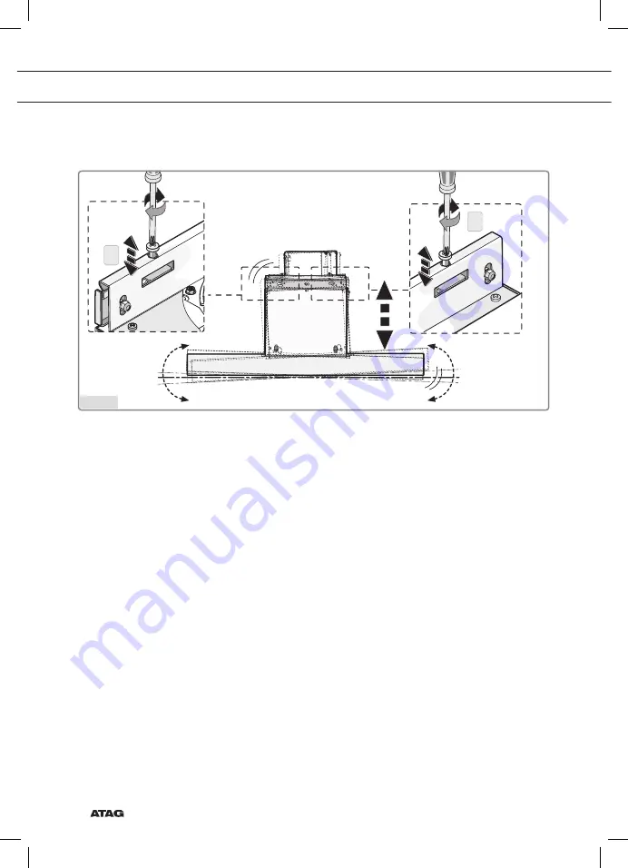
- Align the cooker hood horizontally using the two levelling screws (Figure 7 step 1).
Fig.7
Страница 1: ...WS90 BAM WS10 RAM WS90 SAM WS12 SAM WS15 SAM Gebruiksaanwijzing afzuigkap Notice d utilisation hotte chemin e Anleitung Dunstabzugshaube Instructions for use cooker hood...
Страница 2: ...ilisation FR 3 FR 24 DE Anleitung DE 3 DE 24 EN Manual EN 3 EN 24 Gebruikte pictogrammen Pictogrammes utilis s Benutzte Piktogramme Pictograms used Belangrijk om te weten Important savoir Wissenswerte...
Страница 3: ...gkap Inleiding 4 Gebruik Beschrijving 5 Bediening 6 Reinigen filters 6 Onderhoud Reinigen 9 Verlichting 11 Installatie Algemeen 12 Aansluiting 13 Inbouwafmetingen 14 Montage 15 Technische gegevens 22...
Страница 4: ...at Lees de veiligheidsvoorschriften en hoe u het apparaat moet onderhouden Bewaar de instructies voor installatie en gebruik Dit kan nuttig zijn voor latere raadplegingen Lees voor gebruik eerst de se...
Страница 5: ...Signalering timerfunctie 7 Signalering Clean Air functie 8 Inschakelen en verhoging afzuigcapaciteit 9 Inschakelen timerfunctie Let op Voordat een functie geactiveerd of gedeactiveerd wordt moet de m...
Страница 6: ...ets 2 de afzuigkap uit Druk gedurende minimaal 2 seconden op de toets 2 om de kap ongeacht de afzuigstand uit te schakelen Aantal snelheden wijzigen modellen met 9 snelheden U kunt kiezen tussen 9 sne...
Страница 7: ...ndt wordt de sterkte na het aflopen van de timer automatisch 30 40 teruggeregeld Let op Als de intensiefstand is geselecteerd kunt u de timerfunctie niet activeren Clean Air functie Met de Clean Air f...
Страница 8: ...geheugen door tegelijkertijd onafgebroken op de 2 en 8 toetsen te drukken totdat de koolstoffilter indicatie 3 niet meer knippert Koolstoffilter indicatie inschakelen Druk tegelijkertijd onafgebroken...
Страница 9: ...heidsvoorschriften Afzuigkap Maak de afzuigkap schoon met een sopje en een zachte doek Daarna met schoon water nabehandelen Gebruik geen agressieve schoonmaakmiddelen zoals bijvoorbeeld soda Het lakwe...
Страница 10: ...en Het filter moet met het sluitmechanisme aan de zijkant geplaatst worden Open het sluitmechanisme De nokjes aan de zijkant van het filter vallen hierdoor naar binnen Houd bij het plaatsen van de fil...
Страница 11: ...tfilters en het regenereerbare actieve koolstoffilter goed droog zijn voordat u deze plaatst Vervanging van het koolstoffilter Om het koolstoffilter te vervangen moeten eerst de vetfilters verwijderd...
Страница 12: ...Bij een elektrische keramische of inductiekookplaat moet deze afstand minimaal 55 cm zijn Neem de plaatselijk geldende voorschriften in acht met betrekking tot de beluchting van gasapparaten Hoe korte...
Страница 13: ...t apparaat als volgt aan op het elektriciteitsnet BRUIN L fase BLAUW N nul GEEL GROEN Aarde Controleer tijdens de aansluiting op het lichtnet of de contactdoos is uitgerust met aarde Deze afzuigkap is...
Страница 14: ...gte De minimale afstand tussen de pandragers van het gaskookplaat en de onderrand van de kap is 65 cm Voor gebruik met een elektrisch keramisch of inductiekookplaat bedraagt deze afstand minimaal 55 c...
Страница 15: ...minimale afstand tussen kap en fornuis Fig 1 Positioneer de beugel met verwijzing naar de maten in figuur A en zet hem op zijn plaats met de meegeleverde schroeven en pluggen Fig 2 Plaats het sjabloo...
Страница 16: ...tegen de muur en lijn deze uit met de 2 hoogste gaten Zet de beugel vast met de twee schroeven meegeleverd Voor de montage worden schroeven en expansiepluggen gebruikt die geschikt zijn voor de muur z...
Страница 17: ...fzuigkap en maak hem vast aan de beugel door de moer aan te brengen op de schroef Fig 6 stap 2 Houd een passende moersleutel vast in een hand en gebruik de andere hand om de moer tegen te houden met e...
Страница 18: ...NL 18 INSTALLATIE Lijn de afzuigkap horizontaal uit door middel van de twee nivelleerschroeven figuur 7 stap 1 Fig 7...
Страница 19: ...ticaal uit door middel van de twee stelschroeven in het motorhuis Fig 8 stap 3 Na het stellen van de kap moet u de schroeven volledig vastdraaien zoals weergegeven in figuur 8 stap 4 en doe hetzelfde...
Страница 20: ...NL 20 INSTALLATIE Bevestig de afzuigkap definitief met de twee meegeleverde schroeven en twee ringen figuur 9 stap 2 Fig 9...
Страница 21: ...van een buis Fig 10 Plaats de bovenste schacht in de onderste schacht en plaats die op de behuizing van de kap Schuif de bovenste schacht tot tegen de beugel en zet deze vast met de twee schroeven Fi...
Страница 22: ...oom Geluid Druk Niveau 7 Luchtstroom Geluid Druk Niveau 8 Luchtstroom Geluid Druk Niveau 9 Luchtstroom Geluid Druk 930 m h 71 dB A 425 Pa 220 240 V 50 60 Hz 266 m h 39 dB A 169 Pa 358 m h 47 dB A 315...
Страница 23: ...Geluid Druk Niveau 9 Luchtstroom Geluid Druk Taal Language Nederlands Dutch Keuringstype Approval type Europa EU 266 m h 39 dB A 169 Pa 266 m h 39 dB A 169 Pa 266 m h 39 dB A 169 Pa 220 240 V 50 60 H...
Страница 24: ...at huishoudelijke apparatuur afzonderlijk moet worden afgevoerd Het apparaat mag aan het einde van zijn nuttige leven dan ook niet worden verwerkt via de normale afvalstroom U moet het inleveren bij e...
Страница 25: ...ation Description 5 Commande 6 Nettoyage des filtres 8 Entretien Nettoyage 9 clairage 11 Installation G n ralit s 12 Alimentation 13 Dimensions d encastrement 14 Montage 15 Sp cifications techniques 2...
Страница 26: ...ions de s curit et le mode d entretien de l appareil Conservez les instructions pour l installation et l utilisation de l appareil Elles pourront vous servir de r f rence dans l avenir Avant l utilisa...
Страница 27: ...fichage 6 Signal pour la fonction minuterie 7 Signal fonction Air propre Clean Air 8 Activer et augmenter la capacit d aspiration 9 Activer la fonction minuterie Attention Avant qu une fonction soit a...
Страница 28: ...bri vement sur la touche 2 pour teindre la hotte Appuyez pendant au moins 2 secondes sur la touche 2 pour teindre la hotte quelle que soit la puissance d aspiration Changer le nombre de vitesses mod...
Страница 29: ...sance est automatiquement r duite de 30 40 lorsque la minuterie est teinte Attention Lorsque la position d aspiration intense est s lectionn e il n est pas possible d activer la fonction minuterie Fon...
Страница 30: ...r Nettoyez ou remplacez le filtre au charbon R initialisez la m moire en appuyant en m me temps sans interruption sur les touches 2 et 8 jusqu ce que le t moin 3 du filtre au charbon cesse de clignote...
Страница 31: ...n doux Rincez l eau claire N utilisez pas de produits d entretien agressifs comme la soude de m nage La laque de votre hotte restera rutilante si vous la cirez de temps en temps Hottes en inox Les hot...
Страница 32: ...acer la cassette filtre Placez le filtre dans la hotte avec le dispositif de fermeture sur le c t Ouvrez le dispositif de fermeture De cette fa on les onglets lat raux du filtre sont situ s vers l int...
Страница 33: ...secs avant d tre plac s Remplacement du filtre au charbon Pour remplacer le filtre au charbon retirez d abord les filtres anti graisses de la hotte Faites glisser les deux petites boutons B du filtre...
Страница 34: ...Dans le cas d une cuisini re lectrique vitroc ramique ou induction la distance minimale est de 55 cm Respectez les r glements locaux applicables au d gazage des appareils gaz Plus le tuyau d vacuatio...
Страница 35: ...t tre x cut e comme suit MARRON L phase BLEU N neutre JAUNE VERT Terre Dans l op ration de raccordement lectrique s assurer que la prise de courant est munie d une connexion la terre Cette hotte aspir...
Страница 36: ...ance minimum entre les supports de casseroles de la cuisini re gaz et le bord inf rieur de la hotte est de 65 cm Dans le cas d une cuisini re lectrique vitroc ramique ou induction la distance minimale...
Страница 37: ...pte de la distance minimale entre la hotte et la cuisini re Fig 1 Placez la matrice sur le mur et veillez ce qu elle s aligne sur la ligne pr c demment dessin e sur le mur Dessinez la position des tro...
Страница 38: ...ue contre le mur alignez la avec les deux trous sup rieurs Fixez la avec deux vis fournies Pour l installation utilisez des vis et chevilles d expansion adapt es au type de paroi utilis par ex b ton a...
Страница 39: ...tionnez la hotte et accrochez la au collier en fixant l crou sur la vis Fig 6 tape 2 Tenez une cl molette appropri e dans une main et utilisez l autre main pour maintenir l crou en place avec une deux...
Страница 40: ...FR 18 INSTALLATION Alignez la hotte horizontalement en utilisant les deux vis d alignement figure 7 tape 1 Fig 7...
Страница 41: ...lement en utilisant deux vis de r glage se trouvant dans le bo tier du moteur Fig 8 tape 3 Apr s avoir positionn la hotte vissez compl tement les vis tel qu indiqu la figure 8 tape 4 et r p tez l op r...
Страница 42: ...FR 20 INSTALLATION Fixez d finitivement la hotte en utilisant les deux vis et les deux anneaux bagues fournis fournies avec l appareil figure 9 tape 2 Fig 9...
Страница 43: ...glisser la tige sup rieure dans la tige inf rieure et fixez les sur la carrosserie de la hotte Faites glisser la tige sup rieure jusqu ce qu elle se trouve contre le collier et fixez la avec les deux...
Страница 44: ...eau sonore pression Niveau 6 d bit d air niveau sonore pression Niveau 7 d bit d air niveau sonore pression Niveau 8 d bit d air niveau sonore pression Niveau 9 d bit d air niveau sonore pression 836...
Страница 45: ...Niveau 8 d bit d air niveau sonore pression Niveau 9 d bit d air niveau sonore pression Taal Language Frans French Keuringstype Approval type Europa EU 836 m h 69 dB A 425 Pa 836 m h 69 dB A 425 Pa 8...
Страница 46: ...signifie qu la fin du cycle de vie de l appareil celui ci doit faire l objet d un traitement s lectif et ne peut pas tre mis au rebut avec les ordures m nag res courantes Vous devrez le remettre l un...
Страница 47: ...bzugshaube Einf hrung 4 Gebrauch Beschreibung 5 Bedienung 6 Filter reinigen 8 Pflege Reinigung 9 Beleuchtung 11 Installation Allgemeines 12 Anschluss 13 Einbauma e 14 Montage 15 Technische daten 22 An...
Страница 48: ...eitsvorschriften und die Pflegeanweisungen f r das Ger t Bewahren Sie die Installations und Gebrauchsanleitung auf Diese Informationen k nnen Ihnen sp ter eventuell nochmals von Nutzen sein Lesen Sie...
Страница 49: ...Anzeige Timerfunktion 7 Anzeige Clean Air Funktion 8 Einschalten und erh hen der Absaugkapazit t 9 Timerfunktion einschalten Achtung Bevor eine Funktion aktiviert oder deaktiviert wird m ssen der Moto...
Страница 50: ...en lang gedr ckt um die Abzugshaube unabh ngig von der Absaugstufe auszuschalten Geschwindigkeitsanzahl ndern bei Modellen mit 9 Geschwindigkeiten Sie k nnen sich entscheiden zwischen 9 Geschwindigkei...
Страница 51: ...es Timers automatisch um 30 40 reduziert Achtung Wenn die Intensivstufe eingeschaltet ist k nnen Sie die Timerfunktion nicht aktivieren Clean Air Funktion Mit der Clean Air Funktion wird die Luft in d...
Страница 52: ...er reinigen oder austauschen Setzen Sie den Arbeitsspeicher zur ck indem Sie gleichzeitig die Taste 2 und die Taste 8 so lange gedr ckt halten bis die Kohlefilter Anzeige 3 nicht mehr blinkt Kohlefilt...
Страница 53: ...eichen Tuch Danach mit sauberem Wasser nachbehandeln Verwenden Sie keine aggressiven Reinigungsmittel wie beispielsweise Natriumkarbonat Der Lack der Abzugshaube beh lt seinen Glanz wenn Sie ihn ab un...
Страница 54: ...n Tuch Filterkassette wieder einsetzen Der Filter muss mit dem Verschlussmechanismus seitlich eingesetzt werden ffnen Sie den Verschlussmechanismus Die Nocken an den Seiten des Filters fallen dadurch...
Страница 55: ...Aktivkohlefilter vollkommen trocken sind bevor sie erneut eingesetzt werden Austausch des Kohlefilters Um den Kohlefilter auszutauschen m ssen zun chst die Fettfilter entfernt werden Dr cken Sie die...
Страница 56: ...nem elektrischen keramischen oder Induktionskochfeld muss dieser Abstand mindestens 55 cm betragen Beachten Sie die rtlich geltenden Vorschriften f r die Bel ftung von Gasger ten Je k rzer und je gera...
Страница 57: ...massen durchzuf hren BRAUN L Phase BLAU N Nullleiter GELB GR N Schutzleiter Vergewissern Sie sich beim elektrischen Anschluss dass die Steckdose geerdet ist Diese Dunstabzugshaube ist mit einem Stecke...
Страница 58: ...stabstand zwischen den Topfaufs tzen des Gasherdes und der Unterkante der Abzugshaube betr gt 65 cm F r die Verwendung mit einem elektrischen keramischen oder Induktionskochfeld muss dieser Abstand mi...
Страница 59: ...wischen der Abzugshaube und dem Herd Abb 1 Halten Sie die Schablone gegen die Wand und sorgen Sie daf r dass ihr Umriss mit dem vorher auf die Wand gezeichneten Umriss bereinstimmt Zeichen Sie die Pos...
Страница 60: ...der Wand und richten Sie ihn an den beiden obersten ffnungen aus Sichern Sie ihn mit den zwei mitgelieferten Schrauben F r die Montage werden Schrauben und Spreizd bel verwendet die f r die Wand selbs...
Страница 61: ...gshaube und befestigen Sie diese an der Halterung indem Sie die Mutter auf die Schraube drehen Abb 6 Schritt 2 Benutzen Sie zu diesem Zweck einen passenden Schraubenschl ssel und fixieren Sie die Mutt...
Страница 62: ...DE 18 INSTALLATION Richten Sie die Abzugshaube mithilfe der 2 Ausgleichsschrauben horizontal aus Abb 7 Schritt 1 Abb 7...
Страница 63: ...llschrauben im Motorgeh use auch vertikal aus Abb 8 Schritt 3 Nach dem Ausrichten der Abzugshaube m ssen Sie die Schrauben vollst ndig festziehen wie in Abbildung 8 Schritt 4 dargestellt verfahren sie...
Страница 64: ...DE 20 INSTALLATION Befestigen Sie die Abzugshaube definitiv mit den 2 mitgelieferten Schrauben und 2 Unterlegscheiben Abbildung 9 Schritt 2 Abb 9...
Страница 65: ...Bringen Sie den oberen auf dem unteren Schacht an und installieren Sie diesen auf dem Geh use der Abzugshaube Schieben Sie den oberen Schacht gegen die Halterung und befestigen Sie sie mit den 2 Schra...
Страница 66: ...k Stufe 6 Luftstr mung Ger usch Druck Stufe 7 Luftstr mung Ger usch Druck Stufe 8 Luftstr mung Ger usch Druck Stufe 9 Luftstr mung Ger usch Druck 930 m h 71 dB A 425 Pa 930 m h 71 dB A 425 Pa 790 m h...
Страница 67: ...tstr mung Ger usch Druck Stufe 9 Luftstr mung Ger usch Druck Taal Language Duits German Keuringstype Approval type Europa EU 836 m h 69 dB A 425 Pa 836 m h 69 dB A 425 Pa 836 m h 69 dB A 425 Pa 930 m...
Страница 68: ...nen Abfallcontainer Mit diesem Symbol wird darauf hingewiesen dass Haushaltsger te separat entsorgt werden m ssen Dies bedeutet dass das Ger t am Ende seiner Lebensdauer nicht mit dem normalen Hausm l...
Страница 69: ...hood Introduction 4 Use Description 5 Operation 6 Cleaning filters 8 Maintenance Cleaning 9 Lighting 11 Installation General 12 Connection 13 Build in dimensions 14 Assembly 15 Technical specification...
Страница 70: ...ase read the appliance s safety and maintenance instructions Please retain the operating and installation instructions as these may be useful for future reference Please read the separate safety instr...
Страница 71: ...us 6 Timer function indicator 7 Clean Air function indicator 8 Switching on and increasing air extraction capacity 9 Switching on timer function Note Prior to activating or deactivating a function the...
Страница 72: ...se between 9 speed settings standard or 5 speed settings Press and hold the button 2 and button 8 for at least 5 seconds This selects the 5 speed setting option Press and hold the button 2 and button...
Страница 73: ...function The Clean Air function allows you to freshen the air in your kitchen for a maximum of 12 hours Switch off the cooker hood Press and hold the timer button 9 for approximately 4 seconds The co...
Страница 74: ...ld then be cleaned or replaced Reset the memory by simultaneously pressing and holding the 2 and 8 buttons until the carbon filter indicator 3 stops flashing Switching on carbon filter indicator Simul...
Страница 75: ...and a soft cloth Then wash off with clean water Do not use aggressive cleaning agents such as caustic soda The cooker hood finish stays in good condition if it is buffed periodically following the ap...
Страница 76: ...filter The filter should be placed with the locking mechanism on the side Open the filter access hatch The notches at the side of the filter will then slot in Hold the access hatch in this position w...
Страница 77: ...lters and the regenerable active carbon filter are thoroughly dry before repositioning Replacing the carbon filter The grease filters should first be removed before replacing the carbon filter Press t...
Страница 78: ...ast 65 cm With an electric ceramic or induction hob this distance should be at least 55 cm Follow the applicable local regulations regarding the ventilation of gas appliances The cooker hood will work...
Страница 79: ...ains is carried out as follows BROWN L phase BLUE N zero YELLOW GREEN Earth During the electrical connection make sure that the electrical socket is equipped with earth connection This built in unit h...
Страница 80: ...tion height The minimum distance between a gas hob s pan supports and the lower edge of the hood should be 65 cm For use with an electric ceramic or induction hob this distance should be at least 55 c...
Страница 81: ...count the minimum distance between the hood and the hob Fig 1 Place the template on the wall and ensure that the line corresponds to the line previously drawn on the wall Mark the position of the hole...
Страница 82: ...cket against the wall align it with the two highest holes Secure it with two supplied screws For assembly screws and expansion plugs should be used that are suitable for the wall type for example rein...
Страница 83: ...ion the cooker hood and secure it to the bracket by applying the nut to the screw Fig 6 step 2 Hold an appropriate spanner in one hand and use a second spanner in the other hand to counter the nut Fig...
Страница 84: ...EN 18 INSTALLATION Align the cooker hood horizontally using the two levelling screws Figure 7 step 1 Fig 7...
Страница 85: ...er hood vertically using the two set screws in the motor housing Fig 8 step 3 After levelling the hood you should secure the screws completely as indicated in Figure 8 step 4 and do the same with the...
Страница 86: ...EN 20 INSTALLATION Secure the cooker hood definitively with the two supplied screws and rings Figure 9 step 2 Fig 9...
Страница 87: ...outlet using a tube Fig 10 Place the top shaft in the bottom shaft and put this on the hood s casing Slide the top shaft against the bracket and secure this with the two screws Fig 11 Put the power pl...
Страница 88: ...e Level 8 Air ow Noise Pressure Level 9 Air ow Noise Pressure 836 m h 69 dB A 425 Pa 836 m h 69 dB A 425 Pa 930 m h 71 dB A 425 Pa 930 m h 71 dB A 425 Pa 656 m h 63 dB A 422 Pa 656 m h 63 dB A 422 Pa...
Страница 89: ...Air ow Noise Pressure Taal Language Engels English Keuringstype Approval type Europa EU 836 m h 69 dB A 425 Pa 836 m h 69 dB A 425 Pa 836 m h 69 dB A 425 Pa 930 m h 71 dB A 425 Pa 930 m h 71 dB A 425...
Страница 90: ...aste container This indicates that household appliances must be disposed of separately This means that the appliance may not be processed via the regular waste flow at the end of its useful life You s...
Страница 91: ...EN 25...
Страница 92: ...689660 VER 2 08 07 2021 689660 689660 www atag nl www atag be...