


Last update: 2021/12/20 16:41
ms2000_operation
https://asiimaging.com/docs/ms2000_operation
https://asiimaging.com/docs/
Printed on 2022/03/16 04:45
Two BNC connectors are provided, labeled IN and OUT. The connectors are wired to the internal board
connector SV1. The IN connector is usually wired to IN0, the buffered TTL input channel. On piezo Z-
axis (PZ_* Firmware) systems, the OUT connector is connected to the analog DAC output that is used
for control of the piezo system with a 0-10v analog signal (3mA max). On non-piezo systems, the OUT
connector is usually wired to OUT0, the buffered TTL output channel, and provides a 0 or 5v digital
output.
Reset Button
The reset button causes a hardware-level reboot of the microprocessor, which re-initializes the MS
2000 system.
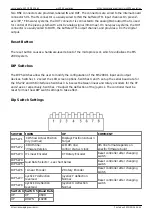
DIP Switches
The DIP Switches allow the user to modify the configuration of the MS 2000’s input and output
devices. Switches 1 2 select the LCD screen options. Switches 4 and 5 set up the serial baud rate for
the RS-232 and USB interfaces. Switches 3 & 6 select between linear and rotary encoders for the XY
and Z axes, respectively. Switches 7 8 adjust the deflection of the joystick. The controller must be
reset for most new DIP switch settings to take effect.
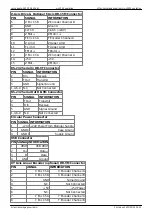
Dip Switch Settings
SWITCH DOWN
UP
COMMENT
DIP SW 1
LCD Show Actual Position
Only (normal)
Displays Position Actual >
Target
DIP SW 2
LCD 4th line:
Firmware Version
LCD 4th line:
config / status / clock
4th line format depends on
specific firmware build
DIP SW 3 XY Linear Encoder
XY Rotary Encoder
Reset controller after changing
switch
DIP SW 4
Baud Rate Selector - see chart below
Reset controller after changing
switch
DIP SW 5
DIP SW 6 Z Linear Encoder
Z Rotary Encoder
Reset controller after changing
switch
DIP SW 7
Joystick Y deflection
Reversed
Joystick Y deflection
Normal
Reset controller after changing
switch
DIP SW 8
Joystick X deflection
Reversed
Joystick X deflection
Normal
Switch 4 Switch 5 Baud Rate
UP
UP
9600
UP
DOWN
19200


