


Operating Manual - Pema Protea Equipped Media Amplifier
6
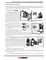
2.3b Firewalls
- If Protea
ne
software does not detect the amplifier or show real time changes, the firewall in the host PC
may need to have Protea
ne
software added to its firewall exceptions, since firewalls may block the amplifier response to the PC.
The current PC firewall status is found by clicking on the Windows Start button, then Control Panel, then double clicking on
the security shield where firewall exceptions are configured.
2.3c Wi-Fi and LAN
– For the initial device auto-configuration process, any secondary Wi-Fi connection should be dis-
abled on the PC, and the LAN (Local Area Network) connection must be enabled on the PC. Secondary network connections
may confuse the auto device discovery process. Go to the Windows Control Panel, then Network Connections, to disable any
secondary network connections. Once communications with the device is established, secondary network connections can be
enabled again.
2.3d Connecting Device(s)
- Connect the Ethernet cable from the PC or network to the amplifier. If a successful Ethernet
connection has been made, a solid green LED (Link) lights up on the amplifier's RJ-45 Ethernet port. If there is no green LED
showing, there is either a problem with the cable or the network source which must be addressed before proceeding further. All
RJ-45 Ethernet ports flash green when active, so backtrack through any other cables, routers, or switches to find the problem.
The flashing yellow LED (Data) indicates that data is flowing to or from the amplifier.
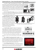
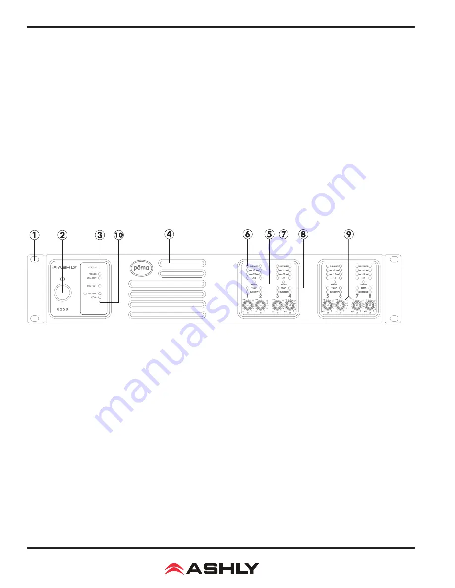
2.4 Front Panel Features
1. Mounting Holes
– For rack mounting.
2. Power Switch
– Switches the unit on or off. Note: The power switch can be disabled from Protea
ne
Software.
3. Status LEDs
– Indicate status of: Power, Standby, Protect, Power Switch Disable, and Com activity.
4. Air Inflow Vents
– Cool air enters here and is vented out through the sides.
5. Channel Controls
– Channel control area.
6. Signal LEDs
– The lowest LED will begin to light when the output voltage reaches -18dBu below rated output. The
Clip LEDs will begin to flash when output voltage is 1/2 volt below the output power supply voltage, or the front end is clipped.
7. Bridge
– This LED indicates that the channel pair is selected to BRIDGE mode from within Protea
ne
software, and that
only the odd input channel level control is active.
8. Temp and Current LEDs
– The Temp LED indicates that the amplifier channel has reached an excessively high oper-
ating temperature and will gradually attenuate the signal to compensate. If unable to sufficiently cool the channel, the amplifier
will eventually go into protect mode. The Current LED confirms that the amplifier output is delivered to a speaker load.
9. Channel Attenuators
– These control the input signal level to the amp, and can be disabled from software.
10. Factory Reset
– To reset all internal configurations (including presets and passwords) back to the original factory set-
tings, press and hold this recessed front panel momentary switch during power up until all channel LEDs sequence from bottom
to top. Upon reset completion, the LEDs will turn off and the amp will be in normal operating mode.


