


3
ADC-02CF
SETUP AND OPERATION
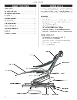
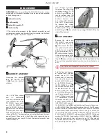
1 UNPACKING:
Using two
people, lift the chair
A
from
the transport case and set it
on the floor.
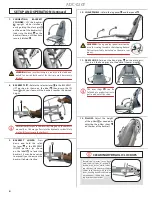
2 MOVING INTO POSITION:
Pull out the stabilizer
A
and
use it as a handle to tilt the
chair up onto its wheels
B
,
then roll the chair to where it
will be used.
WARNING:
The backrest
strap
C
must always be
securely fastened when
tilting the chair upright to
prevent injury or damage
caused by the backrest
suddenly opening.
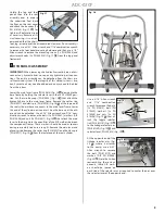
3 CHAIR PREPARATION:
Set the chair down with its feet on the
floor. Make sure that the stabilizer
A
is fully extended. Adjust
the leveling foot
B
as needed to compensate for an uneven
floor. Remove the backrest strap
C
from the chair and save for
reuse.
A
C
B
WARNING:
The stabilizer must be fully extended and the
leveling foot properly adjusted to reduce chair tipping hazard.
The floor under the chair must be hard and level.
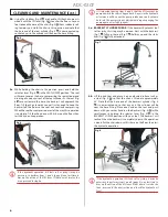
4 SELECTOR LEVER LABELS:
Locate the 2 selector lever labels
A
on opposite sides of the chair base. These labels show the
selector lever positions for lifting and lowering the seat and
the backrest.
A
SEAT
LIFT
L O W E R
BACKREST
LIFT
L O W E R
The selector lever can be operated hands-free from either side
of the chair.
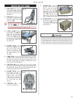
5 SEAT LIFT:
Rotate the selector lever
A
to the SEAT LIFT posi‑
tion (as shown on the label
B
) then pump the lift lever
C
with
your foot until the chair reaches the desired height.
A
B
C
6 SEAT LOWER:
Press down and
hold the selector lever
A
in
the SEAT LOWER position (as
shown on the label
B
) to lower
the chair.
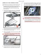
The selector levers can be extended outward to make them easier to
The selector levers can be extended outward to make them easier to
reach. Depress the locking button
reach. Depress the locking button
A
on the selector lever tube, then
on the selector lever tube, then
slide the selector lever out until the locking button pops out of the
slide the selector lever out until the locking button pops out of the
second hole
second hole
B
on the tube.
on the tube.
A
B
EXTENDING THE SELECTOR LEVERS
A
A
B
C
A
B
Содержание ADC-02CF
Страница 14: ...14 ADC 02CF ...
Страница 15: ...15 ADC 02CF ...