


Page 10
Replacing Air Storage Tank Components
Pressure Switch Replacement
Reference Figure F
Tools:
1/8 hex drive or Allen wrench, #2 Phillips screw driver, 12 in. or smaller crescent wrench, thread seal-
ing compound or Teflon tape.
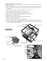
1. Unplug the AA-75CF compressor and drain the air storage tank.
2. Remove compressor chassis from case bottom as per the Compressor Chassis Removal section.
3. Remove four exhaust baffle screws to allow access to the pressure switch screws.
4. Loosen pressure switch cover screw and remove pressure switch cover.
5. Loosen the unloader valve nut and remove unloader tube.
6. Loosen screws on the pressure switch to release the motor power leads, the control wire leads and
the switch ground.
When replacing leads, be sure the wire pair leading through the motor exhaust chassis to the motor
connects to the MOTOR location on the pressure switch and that the wire pair from the control wire
set, contained in polyester braid, connects to the LINE location of the pressure switch. Similar wire
colors should attach on the same side of the pressure switch.
7. Remove pressure relief valve, female quick connect fitting, and pressure gauge.
8. Using the hex of the coupler fitting, turn pressure switch off of the air storage tank. Guide wires
slowly through the 5/8 grommet during the initial turn.
9. Remove the coupler fitting from the pressure switch.
10. Replace pressure switch and reassemble by reversing steps. Use Teflon tape to seal pipe threaded
fittings.
Note:
In addition to exposing wire connections, removing the pressure switch cover exposes a pair of
adjustment screws used to control the AA-75 CF compressor’s cut off pressure and pressure range.
By turning the metal screw clockwise the air storage tank cut off pressure is increased. Turning the
plastic screw clockwise increases the separation between the cut off and cut in pressure. Air storage
tank pressure should never be adjusted to exceed 110 psi.
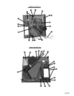
Check Valve Replacement
Reference Figure G
Tools:
12 in. or smaller crescent wrench, Teflon tape or thread sealing compound.
1. Remove compressor chassis from case bottom as per the Compressor Chassis Removal section.
2. Loosen nuts on 1/8 poly fittings and disconnect unloader tube and tank side tank drain tube.
3. Push in the release ring of the push-in elbow fitting on the tank then pull tank/aftercooler tube
loose.
4. Remove push-in elbow fitting and 1/8 tube fitting from the check valve.
5. Remove check valve from the air storage tank.
6. Replace check valve and reassemble by reversing steps. Use Teflon tape to seal pipe threaded
fittings.
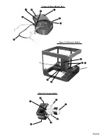
Removing the Air Storage Tank
Reference Figure G
1. Remove compressor chassis from case bottom as per the Compressor Chassis Removal section.
2. Complete Pressure Switch Replacement procedure omitting steps 7, 9 and 10.
3. Complete Check Valve Replacement procedure omitting steps 4 and 6.
4. Remove three tank assembly screws and the 1/8 tube fitting on the tank bottom.
5. Rotate the air storage tank slowly clockwise and remove through the exhaust duct side of the
compressor chassis leading with the tank bottom.
Содержание AA-75CF
Страница 13: ...Page 13 AA 75CF SYSTEM WIRING SCHEMATIC AA 75CF SYSTEM PNEUMATIC SCHEMATIC Figure J Figure K...
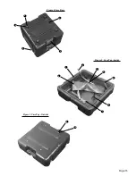
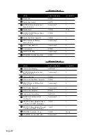
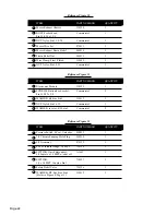
Страница 15: ...Page 15 1 2 3 4 5 2 3 5 8 6 7 4 1 Figure 1 Case Base Figure 2 Case Top Inside 9 10 Figure 3 Case Top Outside...
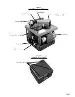
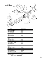
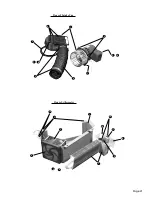
Страница 19: ...Page 19 1 2 7 3 4 6 5 Figure 6 Transformer 1 2 3 4 5 6 7 8 9 10 11 12 Figure 7 Compressor 13...
Страница 21: ...Page 21 1 2 3 4 5 6 7 8 9 10 Figure 8 Intake Fan Figure 9 Aftercooler 1 2 13 3 4 5 6 7 8 9 10 11 12 11...
Страница 27: ...Page 27 Notes...


