Aseptico 6520-01-600-8241 Скачать руководство пользователя страница 7

5

After the ALU-40LED-CF Lamp has been set

up, the unit is ready to operate:

1.

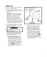
Ensure that the protective Lens Cover is

mounted onto the front of the Lamp Head

(see Figure 4).

IMPORTANT:

If applying light-activated

composites, it is recommended that the

supplied Color Filter, PN: 461974, be

used to filter the light from the ALU-

40LED-CF Lamp. To install the Filter,

remove the Lens Cover and place the

Filter against the inside of the Cover (see

Figure 5, page 6). Center the Filter so that

it completely covers the transparent shield

on the Cover. Replace the Lens Cover. 

2.

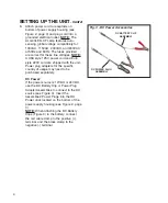
Turn On/Off switch located on bottom of

power supply housing to On (—) position

(see Figure 2, page 3).

3.

Adjust light intensity and spot size by

rotating the two adjustment rings on the

Lamp Head (see Figure 4):

a) LED Intensity Adjustment Ring:

Provides variable brightness control.

When viewed from the rear of the

Lamp Head, rotate Ring clockwise to

increase lamp intensity, or counter-

clockwise to decrease intensity. The

intensity adjustment range is from 0%

to 100%. 

NOTE:

The total adjustment

range of the Intensity Ring covers

approximately 90° of rotation -- do not

OPERATION:

attempt to force the Ring past the

stops at each end of this range.

b) LED Aperture Adjustment Ring:

Allows user to select from seven

different beam aperture sizes. When

viewed from the rear of the Lamp

Head, rotate the Ring counterclock-

wise to increase beam width, and

clockwise to decrease width. 

NOTE:

When the Aperture Ring is rotated

continuously in one direction, the

Lamp will repeatedly cycle through the

seven aperture sizes.

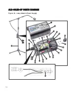
Fig. 4 - Illumination Controls  

LED

INTENSITY

ADJUSTMENT

RING

LED

APERTURE SIZE

ADJUSTMENT RING

PROTECTIVE

LENS COVER

BRIGHTER

BEAM

WIDER

BEAM

WARNING:

Avoid looking directly into LED lamp. Protect

patient with darkened eyewear when directing

light near patient's eyes.

Содержание 6520-01-600-8241

Страница 1: ...ALU 40LED CF Portable Dental Lamp NSN 6520 01 600 8241 OPERATION MAINTENANCE MANUAL ...

Страница 2: ... 3157 Toll Free 800 426 5913 www aseptico com info aseptico com INFORMATION CONCERNING THE ACCURACY AND PRECISION OF THIS PRODUCT MAY BE OBTAINED UPON REQUEST BY CONTACTING ASEPTICO AT THE ADDRESS SHOWN ON THIS PAGE To prevent injury to people and damage to property please heed relevant warnings and remarks They are marked as follows WARNING Serious injury or death may result if ignored CAUTION Da...

Страница 3: ...ions provided in this manual to receive the best and longest service from your Aseptico equipment Separate manuals may be provided to cover the operation and maintenance of other accessories for your unit PACKAGE CONTENTS Portable Dental Lamp Assembly PN 120369 01 Color Filter PN 461974 For use with light activated composites Two 0 160A Spare Fuses PN 830046 DC Battery Power Clip Assembly PN AA 40...

Страница 4: ...ded for operation in the presence of flammable anesthetics or gases CAUTION Connect AC power supply mains cable to a properly grounded outlet only CAUTION The ALU 40LED CF Lamp is sensitive to shock and may be damaged if dropped or impacted against a hard surface WARNING Do not disassemble or alter the Lamp s LED Boom Arm or Power Supply subassemblies CAUTION It is recommended to always have the p...

Страница 5: ...desired height Tighten the handgrip to secure post in place Loosen the boom adjustment handle and extend boom to desired length and or pivot the lamp head to the desired operating position Tighten handle to secure the boom in place SETTING UP THE UNIT Fig 1 System Components POWER SUPPLY TELESCOPING CENTER POST FLEXIBLE GOOSENECK LAMP HEAD w ADJUSTABLE CONTROLS PEDESTAL PEDESTAL ADJUSMENT KNOB CEN...

Страница 6: ...ug adapters for the specific country of usage may need to be purchased separately DC Power If the power source is 12VDC or 24VDC use the DC Battery Clip or Power Plug Adapter Assemblies to connect to the DC source see Figure 3 Insert the Assemblies Power Plugs into the DC Power Jack located on the bottom of the power supply housing see Figure 2 page 3 NOTE When attaching the DC Battery Clips Figur...

Страница 7: ...ariable brightness control When viewed from the rear of the Lamp Head rotate Ring clockwise to increase lamp intensity or counter clockwise to decrease intensity The intensity adjustment range is from 0 to 100 NOTE The total adjustment range of the Intensity Ring covers approximately 90 of rotation do not OPERATION attempt to force the Ring past the stops at each end of this range b LED Aperture A...

Страница 8: ...outer shelf on the Front Housing see Figure 7 e Attach Lens to Housing with the three Fasteners from Step 1c above f Replace Lens Cover 2 LENS ADJUSTMENT Follow these steps to adjust the position of the Lens so that it emits the sharpest beam refer to Figures 6 7 a Position Lamp Head approximately 28 71 cm away from a flat test surface Turn Lamp On and observe sharpness of projected light beam see...

Страница 9: ...f dish soap to a lint free lens tissue and gently wipe Lens Clean the Lens Cover using the same method Reinstall Fresnel Lens and Lens Cover onto Lamp Head b Metal Components The metal exterior may be cleaned by wiping with a soft cloth moistened with mild detergent or disinfecting solution such as isopropal alcohol c Gooseneck Electrical Cords Turn Lamp power Off Wipe down the gooseneck and elect...

Страница 10: ...8 ALU 40LED CF PARTS DIAGRAM Figure 9 Lamp Stand Boom ALU 40LED CF LAMP HEAD Refer to Figure 11 page 12 2 3 4 5 6 7 9 11 10 8 12 13 5 11 1 ...

Страница 11: ...3 1 SET SCREW CONE PT HEX SOC M6 X 8MM BLK 510731 1 HEAT SHRINK 1 8 BLK 870118 1 HEAT SHRINK 1 4 BLK 870120 2 5 HOLE PLUG NYLON 1 2 IN BLACK 510202 1 M S STNLS PHDPHL 10 24 X 5 8 THRD CUTTING 510732 1 END CAP MODIFIED BOOM ALU 40 461959 1 CABLE COILED 2 CONDUCTOR ALU 40LED CF 870319 1 HANDLE CLAMP LEVR M8X1 0 FEM THRD BLK 850076 1 CLAMP BOOM ALU 40 LED 730646 1 1 2 3 4 5 6 7 8 9 10 11 12 13 Cont d...

Страница 12: ...10 ALU 40LED CF PARTS DIAGRAM Figure 10 Lamp Stand Power Supply 15 16 20 23 24 41 19 18 37 21 16 33 36 28 35 34 26 27 28 23 25 32 32 29 30 40 38 39 42 17 22 ...

Страница 13: ... 1 WIRE PVC 22 GRN YEL 54 870260 0 21 CONN JACK DC POWER PCB MOUNT 860333 1 FUSE 5 X 20 SLO BLO 0 160 AMP 830046 2 FUSE DRAWER 2 POLE 840060 1 POWER INLET FUSED SWITCHED 840059 1 POWER SUPLY 12VDC 0 83A INPUT 85 264 VAC 840112 1 NUT NYLON 4 40 510554 4 WASHER FLAT NYLON 120IDX 250 ODX 0 510127 4 SPACER NYLON 1 4 RND X 7 16 L 6 510267 4 BASE POWER SUPPLY ALU 40LED CF 461944 1 STAND ALU 27 29 AKG BL...

Страница 14: ...12 Figure 11 Lamp Head 2 4 5 8 9 18 17 6 3 6 7 10 11 13 19 16 15 1 21 12 20 14 ...

Страница 15: ...488 1 WASHER SHIM 43 OD X 115 ID X 01 STNLS 510726 1 APERTURE ADJUST RING ALU 40LED CF 461931 1 RES 100K TRIM POT 350V 1 2W 810430 1 WIRE 24 TEFLON 41 40 TINNED COPPER WHT 870314 2 WIRE 24 TEFLON 41 40 TINNED COPPER BLK 870320 2 PCB ASSY LAMP HEAD ALU 40LED CF 330578 1 FTN UNIVERSAL JOINT M10 1 0 MALE THRDS 730643 1 WASHER 6 NYL 140 ID X 312 OD X 032 THK 510573 1 REAR HOUSING PLATE ALU 40LED CF 46...

Страница 16: ...y up Replace fuses 0 160 Amp 5 x 20mm 250V slo blow Check plug and electrical source Turn intensity up Clean Lens Cover and or Fresnel Lens Note Before cleaning turn power to Lamp Off Check plug and electrical source LED Assembly might be damaged Return entire Lamp Assembly to Aseptico for repairs Replace both fuses 0 160 Amp 5 x 20mm 250V slo blow ...

Страница 17: ...ter 5 72 cm to 11 74 cm Adjustable 27 56 in 70 cm focal length Beam Characteristics Color temperature 6 500 Kelvin Light Output 1 500 ft c 24 Typ 16 145 lux 61 cm Typ Light Distribution 7 different aperture sizes Nominal Working Distances 16 40 6 cm w large aperture or 36 91 4 cm w small aperture Light Source LED Emitter 1013 3 hPa 697 hPa 10 90 10 C 50 F 45 C 113 F OPERATING TEMPERATURE 20 C 4 F ...

Страница 18: ...ntion consult accompanying documents Type B Equipment Do Not Throw Into Trash Class II Equipment Manufacturer Authorized European Representative Protective Earth Ground Temperature Limitation Atmospheric Pressure Limitation Humidity Limitation Fuse Rating 0 160A 2X ...

Страница 19: ...iter of such action In the event of alleged defect under warranty the purchaser is to notify Aseptico s Customer Service Department promptly Customer Service will provide instructions usually directing that the product be returned for service Shipment to Aseptico and the cost thereof is always the responsibility of the purchaser Accidental misuse inappropriate installation or failure to perform di...

Страница 20: ...P N 420914 Rev G ECO 14684 03 2019 PRINTED IN THE USA P O Box 1548 Woodinville WA 98072 8333 216th Street S E Woodinville WA 98072 425 487 3157 800 426 5913 www aseptico com info aseptico com ...

Отзывы: