


I&M No.V5744-Sec.1
50 Hanover Road, Florham Park, New Jersey 07932 www.ascovalve.com
Page 2 of 4 (Section 1 of 2)
Temperature Limitations
Valves with design change letter K" or P" within the catalog number
(example: 8344K074) have a maximum fluid temperature of 180
_
F. Refer to
separate solenoid Installation and Maintenance Instructions for maximum
ambient temperature.
Future Service Considerations
Provision should be made for performing seat leakage, external leakage, and
operational tests on the valve with a nonhazardous, noncombustible fluid
after disassembly and reassembly.
Cleaning
All pneumatic operated valves should be cleaned periodically. The time
between cleanings will vary depending on the medium and service conditions.
In general, sluggish valve operation, excessive noise or leakage will indicate
that cleaning is required. In the extreme case, faulty valve operation will
occur and the valve may fail to shift. Clean stainer or filter when cleaning the
valve.
Preventive Maintenance
S
Keep the medium flowing through the valve as free from dirt and foreign
material as possible.
S
While in service, the valve should be operated at least once a month to
insure proper opening and closing.
S
Depending on the medium and service condition, periodic inspection of
internal valve parts for damage or excessive wear is recommended.
Thoroughly clean all parts. If parts are worn or damaged, install a
complete ASCO Rebuild Kit.
Causes Of Improper Operation
S
Incorrect Pressure:
Check valve pressure. Pressure to valve must be
within range specified on nameplate.
S
Excessive Leakage:
Disassemble valve and install a complete ASCO
Rebuild Kit.
Valve Disassembly for 1/4
I
, 3/8
I
and 1/2
I
NPT Valves
1. Disassemble valve in an orderly fashion using exploded views for
identification of parts.
2. Remove solenoid, see separate instructions.
3. Unscrew solenoid base sub-assembly. For AC/DC Construction,
remove core assembly with spring, core guide and body gasket.
4. A 4-40 machine screw provided in ASCO Rebuild Kit serves as a
self-tapping screw to remove insert from body. Thread screw a few
turns into through hole located in flat surface of the insert.
CAUTION: Do not damage center hole (pilot orifice) in
raised surface of insert.
5. Remove insert by using a pair of pliers to grip the head of the screw.
Then pull insert with gaskets from body insert cavity.
6. Remove three gaskets from insert. Tag each as they are removed so
that they can be reassembled in the same location. Middle and lower
gaskets are the same size, however, the lower gasket is a softer material.
7. Remove body screws/lockwashers (4) from piston end body. Slip
piston end body off piston/shaft sub-assembly.
8. Slide piston/shaft sub-assembly from main valve body. The
piston/shaft sub-assembly is comprised of the main shaft, locknut,
shaft gasket, piston, body u-cup, guide u-cup, u-cup o-ring (only
present in 3/8
I
or 1/2
I
NPT valves with 3/8
I
orifice), piston end guide,
guide gaskets (2) and resilient disc.
9. Remove guide gaskets (2), one from either side of piston end guide.
10. Disassemble piston/shaft sub-assembly by inserting a brass rod (of
suitable size) in cross hole in shaft. Rod must be brass or other soft
material so as not to burr the edges of hole. Hold piston shaft firmly
(with rod) and unscrew locknut. Disassemble piston/shaft
sub-assembly in an orderly fashion. Do not damage or mar any of the
parts.
11. Remove locknut, shaft gasket, piston with body and guide u-cups (2)
attached. Slide piston end guide and resilient main disc off main shaft.
12. Remove body u-cups and guide u-cup from piston. For 3/8
I
or 1/2
I
NPT valves with 3/8
I
orifice, remove u-cup o-ring from guide
u-cup.
13. Unscrew seat from opposite end of main body. Remove large and
small seat gaskets (2) from seat. Then remove resilient main disc from
body bore.
14. All parts are now accessible to clean or replace. If parts are worn or
damaged, install a complete ASCO Rebuild Kit.
Valve Reassembly for 1/4
I
, 3/8
I
and 1/2
I
NPT Valves
1. Lubricate large and small seat gaskets, upper, middle, and lower insert
gaskets with DOW CORNING
r
200 Fluid lubricant or an equivalent
high-grade silicone fluid lubricant.
2. Lubricate all remaining gaskets, u-cups, bores of piston, piston end
body, main disc sliding area on the main shaft and valve body insert
cavity with a light coat with DOW CORNING
r
111 Compound
lubricant.
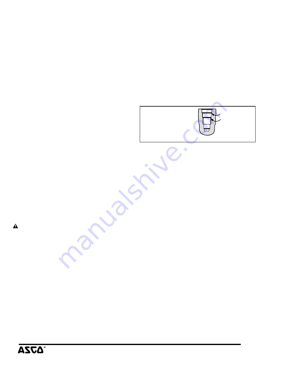
30
_
chamfer
lubrication
points
Partial cutaway view
of valve body to
show insert cavity
lubrication points.
Figure 1. Lubrication of body insert cavity.
3. Preassemble piston/shaft sub-assembly as follows:
A. Position resilient main disc on main shaft so that resilient side of
main disc is facing the piston end guide.
B.
Position piston end guide on main shaft.
C. Install body u-cup and guide u-cup onto piston. Open end of
guide u-cup faces the main valve body, while open end of body
u-cup faces the piston end body. For 3/8
I
or 1/2
I
NPT valves
with 3/8
I
orifice, install a u-cup o-ring inside the guide u-cup.
D. Position piston assembly on main shaft.
E.
Replace shaft gasket and locknut. Tighten locknut while holding
the main shaft as described in
Valve Disassembly
section step 10.
For 3/8
I
and 1/2
I
NPT valve with 3/8
I
orifice, torque locknut to
125 ± 10 in-lbs [14,1 ± 1,1 Nm]. For 1/4
I
or 3/8
I
NPT valve with
1/4
I
orifice, torque locknut to 50 ± 5 in-lbs
[5,7 ± 0,6 Nm].
F.
Position guide gaskets (2) one on guide facing piston end body,
the other in counterbore of main valve body.
4. Install piston/shaft sub-assembly into main valve body.
5. Install small body gaskets (2) into counterbores in piston end body.
6. Slip piston end body over piston/shaft sub-assembly and replace body
screws with lockwashers (4). Torque screws in a crisscross manner to
40 ± 5 in-lbs [4,5 ± 0,6 Nm].
7. Install resilient main disc at opposite end of main shaft; be sure
resilient side is facing seat.
8. Install seat with large and small seat gaskets attached. Torque seat to
40 ± 5 ft-lbs [54,2 ± 6,8 Nm].
9. Position lower insert gasket and disc holder spring in body insert cavity.
10. Snap upper and middle insert gaskets into grooves of insert. Lower
insert gasket fits into the recess between the lower corner of the
insert
and the lower corner of the body insert cavity. Middle and lower insert
gaskets are the same size. However, the lower gasket is made of a softer
material.
11. Place disc holder sub-assembly into insert. Install insert (with gaskets
and disc holder assembly) into body insert cavity, making certain that
the disc holder spring is centered. Rotate this assembly slightly while
pushing downward to aid installation.


