


AT32WB415
Series Reference Manual
2022.04.13
Page 170
Ver 2.00
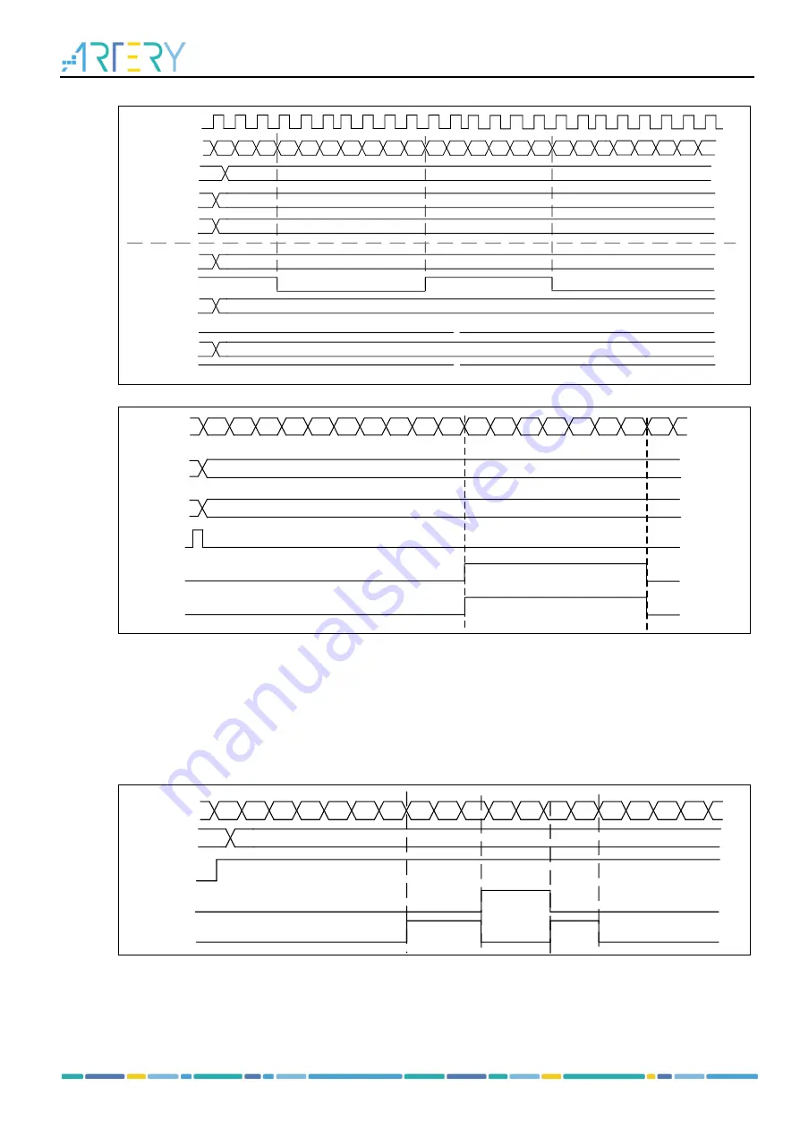
Figure 14-18 Up/down counting mode and PWM mode A
0
1
2
3
...
31
32
31
30
...
3
2
1
0
1
2
3
...
COUNTER
31
32
31
30
30
PR[15:0]
C1ORAW
TMR_CLK
0
DIV[15:0]
32
110
C1OCTRL[2
:
0]
3
C1DT[15
:
0]
C1ORAW
0
0
CIDT[15
:
0]
1
C1ORAW
≥
32
C1DT[15
:
0]
Figure 14-19 One-pulse mode
0
1
2
3
4
5
6
...
40
41
42
43
44
...
5F
60
61
0
COUNTER
61
PR[15
:
0]
42
C1DT[15
:
0]
TRGIN
C1ORAW
C1OUT
CxORAW clear
When the CxOSEN bit is set, the CxORAW signal for a given channel is cleared by applying a high level
to the EXT input. The CxORAW signal remains unchanged until the next overflow event.
This function can only be used in output capture or PWM modes, and does not work in forced mode.
shows the example of clearing CxORAW signal. When the EXT input is high, the CxORAW
signal, which was originally high, is driven low; when the EXT is low, the CxORAW signal outputs the
corresponding level according to the comparison result between the counter value and CxDT value.
Figure 14-20 Clearing CxORAW(PWM mode A) by EXT input
0
1
2
3
4
5
6
7
8
9
A
B
C
D
0
1
2
3
COUNTER
CxOSEN
7
CxDT
EXT
CxORAW
14.1.3.5 TMR synchronization
The timers are linked together internnaly for timer synchronization. Master timer is selected by setting
the PTOS[2: 0] bit; Slave timer is selected by setting the SMSEL[2: 0] bit.
Slave mode include:


