


Page 21
FiberLink 5200 Series User’s Manual
FIberLink 5200 Series
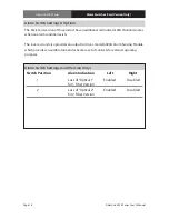
Certifications
Maintenance and Repairs
The FiberLink 5200 Series has been manufactured using the latest semiconductor devices
and techniques that electronic technology has to offer . They have been designed for long,
reliable and trouble-free service and are not normally field repairable .
Should difficulty be encountered, Artel Video Systems maintains a complete
service facility to render accurate, timely and reliable service of all products .
The only maintenance that can be provided by the user is to ascertain that optical
connectors are free of dust or dirt that could interfere with light transmission and that
electrical connections are secure and accurate . Please see the Troubleshooting section of
this manual for additional information .
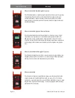
An optical power meter, such as the FiberLink 6650, a visible light source, such as the
FiberLink 6656, and a Two Wavelength Light Source, such as the FiberLink 6652/6654, can
greatly assist and expedite troubleshooting of fiber optic transmission systems and are
recommended tools all installers should have available .
All other questions or comments should be directed to our Customer Service Department .
It should be noted that many “problems” can easily be solved by a simple telephone call .
If you suspect your problem is caused by the optics or the fiber optic cable, and you have
an optical power meter, please take the appropriate measurements prior to contacting
support .
Maintenance and Repairs | Certifications