background image

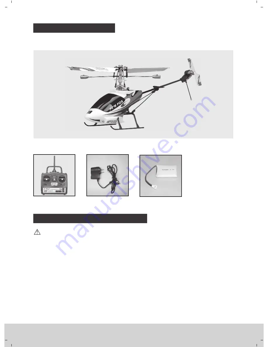
PARTS LIST

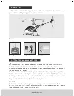
Fuselage

The  helicopter  includes  the  following  parts,  please  check  to  make  sure  that  all  of  the  parts  are  included  in 

your kit. If there is anything missing please contact your local dealer.

OPERATION MANUAL METHOD

1. Put the helicopter on the flat ground and put the transmitter one meter away from the helicopter.

2.  You  can  find  that  the  indicator  light  of  controlling  board  will  flash  by  the  transparent  window  in  the  right  side  of 

fuselage after connecting the power.

3. Turn on the switch of transmitter, the indicator light of transmiter start to flash  in red light and green light in turn.

4. If the indicator light of the controlling board will turn to solid red and the indicator light of the transmitters turn 

to  solide  green  after  7  seconds  and  you  can  hear  Crunch  of  the  servo’s  movement(  the  servo  will  move  to  the 

center), it means the helicopter is ready for flying. After self-inspection, you can start to fly. Otherwise, cut down 

the power for the helicopter and transmitter, then repeat the step from 1 to 4. 

Caution!

1. Do not move or shack helicopter during the process of starting up, which may lead to abnormal flight.

2. Before starting the operation, it should be confirmed that there are no RC aircraft doing the same operation 

inside 30 meters, otherwise, the helicopter may lose control.

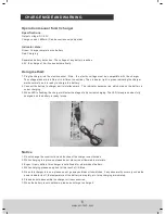
AC Charger

Li-po battery

Transmitter

Please follow the following process before starting, Otherwise, it may lead to the helicopter not to work. 

www.art-tech.com

8

Содержание fire fox

Страница 1: ...Remote control helicopter Remote control helicopter www art tech com Instruction manual ...

Страница 2: ... 03 INSTALLATION 12 NORMAL FLIGHT 11 09 ADJUST THE SPEED OF THE ROTOR BLADES BY THE PCB BOARD MAIN ROTOR BLADE ADJUSTMENT 10 THE POSSIBLE PROBLEMS AND SOLUTIONS 15 PARTS LIST 08 FUNCTIONS FOR CONTROL SET 09 PARTS REPLACING 14 GROUND EFFECT 10 SWASHPLATE ADJUSTMENT 10 OPERATION MANUAL METHOD STARTING PROCEDURE 08 CATALOG www art tech com ...

Страница 3: ...s helicopter Do not touch the rotor blades when it is under rotation www art tech com 3 100 PRODUCT CHARACTER Accomplishment Difficulty of assembly Difficulty of maintain Difficulty of control Anti shatter With the unique mechanical balance structure this model has a characteristic of superb stale flight which is closed to coaxial helicopter Equipped with a built in piezoelectric gyro sensor to en...

Страница 4: ...of safe operation Any damage neglect or unfamiliar use of this product can cause unexpected accidents or injury Please make sure the flying is safe and we are not responsible for any accident 1 Locate an appropriate place to fly your helicopter R C helicopters are capable of flying at high speeds thus posing a certain degree of potential danger to both the flyer and bystanders so it is important t...

Страница 5: ... face eyes and loose clothing away from the blades and gears to avoid being hurt or any damage to the model Your new helicopter is a hi tech electronic device so try to keep the model away from the humidity condition which may result in the operation errors or some other unrespectable faults to the model Never subject your model to severe weather such as raining thunder Fire Fox The helicopter wil...

Страница 6: ...the temperature of the battery rise rapidly etc stop charging immediately 6 Please do not disassemble the charger or its accessories 7 When the battery is not cool down please do not urge to charge it Do not change the construction and function of the charger unauthorized www art tech com 6 Operation manual for AC charger 1 Plug the charger into the electric socket Note the electric voltage must b...

Страница 7: ...o not use the abnormal battery 18 Do not use or keep the battery under the sunlight 19 Do not use the battery nearby the place where generates static electricity over 64V 20 Do not charge the battery when the environmental temperature is under 0 or over 45 21 If you find the battery leaking smelling or abnormal stop using it 22 Keep the battery away from the children 23 Use the specified charger a...

Страница 8: ...he controlling board will turn to solid red and the indicator light of the transmitters turn to solide green after 7 seconds and you can hear Crunch of the servo s movement the servo will move to the center it means the helicopter is ready for flying After self inspection you can start to fly Otherwise cut down the power for the helicopter and transmitter then repeat the step from 1 to 4 Caution 1...

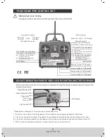
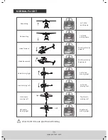
Страница 9: ...ustomer need not adjust it www art tech com 9 Please refer to the page 13 for the position of servos and motor Configured with 2 4G radio control system from about 40 meters Mode 2 left hand throttle The head turn left The head turn right Increase the power Decrease the power Move forward Move left Move right Move backward Please put the throttle joystick in the lowest position before flying Adjus...

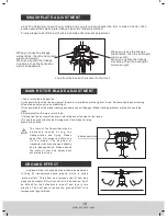
Страница 10: ...er may be Airplane will be influenced by the airflow when airplane is flying 30 centimeters above ground which is called ground effect This effect can increase the lift and also make the helicopter difficult to control in the situation It will be difficult for the helicopter to take off and land in this situation The best way to reduce the ground effect is to increase the flight altitude SWASHPLAT...

Страница 11: ...ning right Head forward Head backward Left stick pushing up Left stick pulling down Left moving left stick Left moving right stick Right moving left stick Right moving right stick Helicopter moving left Helicopter moving right www art tech com 11 Pull the left stick upward Pull the left stick downward ...

Страница 12: ...INSTALLATION www art tech com 12 ...

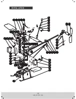
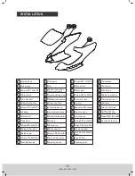
Страница 13: ...ilizer Screw PM1 4x3xD2 5 Balance bar steel Balance bar Screw PB1 2x5xD2 5 Mall ball buckle 3 6g servo Arm Grip connecting steel Stabilizerlinkagesteel Protection fork Versatile board Inner swash plate Swash plate bearing Bearing Servo slice Ball connector Screw PM1 2x4xD2 5 Outer swash plate Spacing sleeve Screw PB1 7x10xD3 Main motor Motor gear Screw PB1 4x4xD2 5 Control board Frame Topcoverofth...

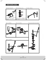
Страница 14: ...wash plate assembly Tail beam assembly Landing ski tail supporting bar tail supporting bar bracket Press A into B then press B set to C and at last press C set into D Motor installation Mervo installation Main shaft and shaft core assembly Stabilizer assembly ...

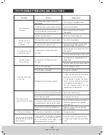
Страница 15: ...10 Make the connection of the body and frame firm enough Change the battery Close the window door switch off the air conditioner or select a more suitable place Change the rotor blades Just change the tail motor Change the tail blades Assemble the stabilizer linkage rightly please see page 10and page 14 Adjust the swash plate please see page 10 Adjust the swash plate please see page10 Check the ba...

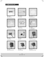
Страница 16: ...No 41047 Main shaft set No 41057 Red main blades set No 41067 Stabilizer set No 41077 Main rotor grip set No 41087 Red Canopy set No 41097 Blue Canopy set No Blue 41157 Tail No Blue 41137 main blades set No 41017 Tail motor frame set SPARE PARTS LIST www art tech com 16 ...

Страница 17: ... 7V 420mAh Battery set No 3R071 Control board No 36075 Chinese type charger No American type charger 36076 No UK type charger 36077 No 41117 Swash plate set No 35071 Servo set No 41107 Slowness gear set No 3A02B Tail motor set No European type charger 36078 No 3A02A Main motor set ...

Страница 18: ...SHENZHEN ART TECH HOBBY INC ...

Отзывы: