4
dc1762afb
DEMO MANUAL DC1762A
Software
The DC890 is controlled by the PScope System Software
provided or downloaded from the Linear Technology
website at http://www.linear.com/software/. If a DC890
was provided, follow the DC890 Quick Start Guide and
the instructions below.
To start the data collection software if PScope.exe, is in-
stalled (by default) in \Program Files\LTC\PScope\, double
click the PScope icon or bring up the run window under
the start menu and browse to the PScope directory and
select PScope.
If the DC1762A demonstration circuit is properly connected
to the DC890, PScope should automatically detect the
DC1762A, and configure itself accordingly. If necessary
the procedure below explains how to manually configure
PScope.
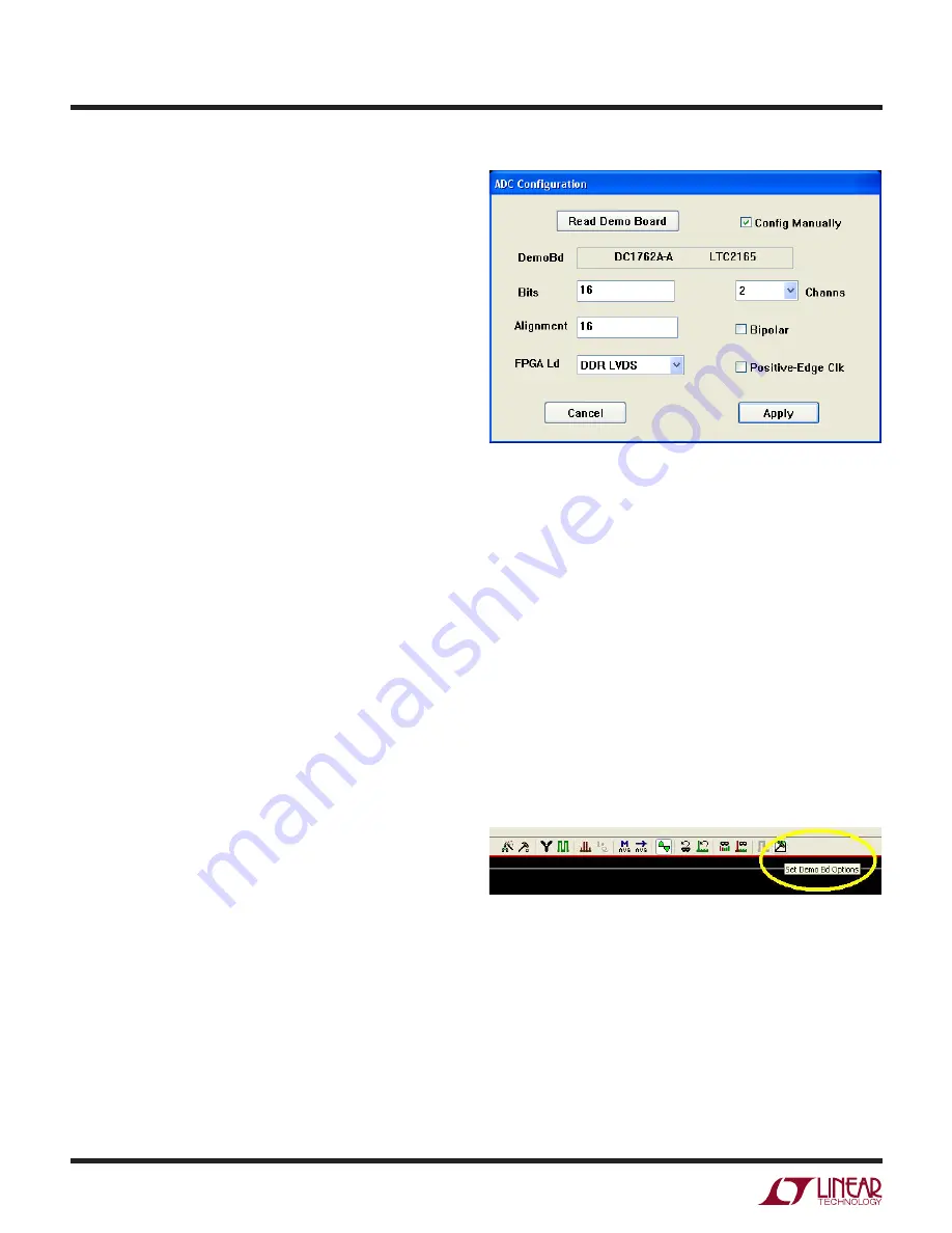
Under the Configure menu, go to ADC Configuration…
Check the Config Manually box and use the following
configuration options, see Figure 2.
Manual Configuration settings:
Bits: 16
Alignment: 16
FPGA Ld: DDR LVDS
Channs: 2
Bipolar: Unchecked
Positive-Edge Clk: Unchecked
If everything is hooked up properly, powered and a suit-
able convert clock is present, clicking the Collect button
should result in time and frequency plots displayed in
the PScope window. Additional information and help for
PScope is available in the DC890 Quick Start Guide and in
the online help available within the PScope program itself.
Serial Programming
PScope has the ability to program the DC1762A board
serially through the DC890. There are several options
available in the LTC2165 family that are only available
through serially programming. PScope allows all of these
features to be tested.
These options are available by first clicking on the Set
Demo Bd Options icon on the PScope toolbar (Figure 3).
This will bring up the menu shown in Figure 4.
Figure 2: ADC Configuration
Figure 3: PScope Toolbar
Quick start proceDure


