background image

28

Step 15

A28

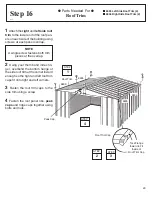
 Parts Needed For 

Ridge Caps & Panels

 8840 Ridge Cap (1)

 7483 Roof Panel (2)

 8486 Ridge Cap (1)

Install the first 

ridge cap 

on the

completed roof section using bolts
and nuts. Fasten roof panel overlaps
not used for ridge cap.  Cover the
head of bolt with the 2" (5,1 cm) piece
of weather stripping tape.  Do not
fasten the ends of the ridge cap at this
time.

Install the second 

ridge cap

 over-

lapping the first ridge cap while in-
stalling the remaining narrow 

roof

panels

.  Continue weather stripping

the ridge.

Fasten the lower end of the panels

to the side wall angles using screws
and washers.  Use bolts and nuts
through wall angle overlaps at the
bottom of the panel.

STEP

1

8840

Strips

STEP

2

7483

8486

Cut Weather

Stripping and

Fold Under

7483

3

STEP

Содержание 697.68538-A

Страница 1: ...7 3 cm x 235 6 cm 313 1 cm 241 9 cm 180 0 cm 300 4 cm 228 6 cm 176 8 cm 141 0 cm 147 3 cm 709290410 Missing Parts Questions on Assembly Call 1 800 851 1085 Do not return to dealer they are not equipped to handle your requests Storage Area 74 Sq Ft 401 Cu Ft 6 9 m2 11 4 m3 BUILDING DIMENSIONS Size rounded off to the nearest foot CAUTION SOME PARTS HAVE SHARP EDGES CARE MUST BE TAKEN WHEN HANDLING T...

Страница 2: ...ble by mail order or at your local dealer or you may construct a base and anchoring system of your choice Your assembly instructions provide information on a few methods commonly used to secure and level a storage building Parts and Parts List Check to be sure that you have all the necessary parts for your building All part numbers can be found on the parts All of these numbers before the must agr...

Страница 3: ...mwork Whenever possible two or more people should work together to assemble your building One person can position parts or panels while the other is able to handle the fasteners and the tools Tools and Materials These are some basic tools and materials you will need for the construction of your building Decide which method of anchoring and the type of base you wish to use in order to form a comple...

Страница 4: ...ntrate your total weight on the roof of the building When using a step ladder make sure that it is fully open and on even ground before climbing on it Keep children and pets away from worksite to avoid distractions and any accidents which may occur Do not attempt to assemble the building if parts are missing because any building left partially assembled may be seriously damaged by light winds Call...

Страница 5: ...ricate door track annually with furniture polish or silicone spray Keep doors closed and locked to prevent wind damage Fasteners Use all washers supplied to protect against weather infiltration and to protect the metal from being scratched by screws Regularly check your building for loose screws bolts nuts etc and retighten them as necessary Moisture A plastic sheet vapor barrier placed under the ...

Страница 6: ... lag bolt into a concrete slab Full assembly instructions and a 1 4 masonary drill bit are included TOOL HANGING RACK Model No TH100 The perfect tool organizer Twin 25 1 2 64 8 cm steel channels plus five heavy duty snap in hangers and a small tool holder for screwdrivers pliers etc Holders slide along channel for fully adjustable spacing Great for garage basement or the back of any door Fits all ...

Страница 7: ...THIS PAGE WAS LEFT BLANK INTENTIONALLY 7 ...

Страница 8: ...THIS PAGE WAS LEFT BLANK INTENTIONALLY 8 ...

Страница 9: ...easure 16 24 40 6 cm 61 0 cm sections to construct inside frame see diagram Secure plywood to frame using 4 penny galvanized nails Allow 6 7 hours for construction OPTION 3 Concrete Slab The slab should be at least 4 10 2 cm thick It must be level and flat to provide good support for the frame The following are the recommended materials for your base 1 x 4 s 19 mm x 89 mm will be removed once the ...

Страница 10: ...on instruction AnchoringintoConcrete 1 For poured concrete slab or footing or patio blocks Use 1 4 x 2 6 mm x 51 mm Lag Screws 2 For Anchor Post of Concrete poured after building is erected Use 1 4 x 6 6 mm x 152 mm Lag Screws ArrowAnchoringKit ModelNo AK4or60298 Recommended for use with any suggested base Contains 4 Anchors with Cable Clamps and installation instruction AnchoringintoWood Post Use...

Страница 11: ... 66183 Roof Trim Cap 2 right 2 left 66045 Handle 2 66646 Washer 369 10 sheets of 40 65109 8 32AcornNut 4 PackedwithScrews 67468 Peak Cap 2 ArrowLogo 65004 8Ax5 16 8mm Screw 326 65923 8 32x3 8 10mm Bolt 161 65900A 10Bx1 2 13mm BlackScrew 8 PackedwithScrews 65103 8 32HexNut 161 Hardware A11 6228 Track Support 2 66769 Door Slide 4 ...

Страница 12: ...k Splice 1 11 9366 Door Track 2 12 8995 Wall Panel 6 13 6529 Roof Panel 2 14 6635 Gable Brace 2 15 10489 Right and Left Doors 2 16 7483 Roof Panel 4 17 9900 Door Jamb 2 18 9917 Rear Wall Channel 2 19 8468 Right Roof Panel 2 20 8469 Left Roof Panel 2 21 8485 Left Side Roof Trim 2 22 8840 Ridge Cap 1 23 10470 Roof Beam 8 24 8836 Right Side Roof Trim 2 25 9922 Side Wall Channel 4 26 8839 Side Wall An...

Страница 13: ...9 16 13 20 21 22 27 23 23 32 32 32 32 2 2 12 2 2 12 12 12 12 12 26 26 26 26 3 3 4 4 11 11 10 17 17 31 9 9 15 1 1 15 8 8 28 29 29 31 31 31 30 25 25 5 5 18 18 30 25 25 8 8 24 21 7 24 23 23 23 23 23 16 23 16 19 20 14 14 6 6 7 13 16 ...

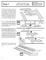
Страница 14: ...hese pieces will align when the pieces are positioned with cor rect amount of overlap See the illus trations below for the proper overall lengthofthesideandrearfloorframes Join the frames by inserting four five bolts into each frame set as shown 3 Double check the length of each and set these pieces aside for later use Step 1 A14 Parts Needed For Floor Frame Assemblies 8934 Ramp 1 9367 Front Floor...

Страница 15: ...all angle pieces as shown in the figure and fasten them together with one bolt in the center hole 4 Make two side wall angles by overlapping the side wall angle piec esasshown Fasteneachsettogeth er with one bolt in the center hole 5 Double check the length of each and set these pieces aside for later use 5986 Rear Wall Angle 2 9917 Rear Wall Channel 2 9922 Side Wall Channel 4 8839 Side Wall Angle...

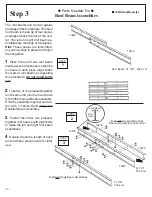
Страница 16: ...t 2 Take two of the pressed together roof beams and join them as shown toformthemainroofbeamassembly Hold the assembly together and fas ten with 14 bolts Build only one Doubled Beam Assembly 3 Fasten the other two pressed together roof beams with eight bolts to make the left and right roof beam assemblies 4 Double check the length of each and set these pieces aside for later use Step 3 D16 Parts N...

Страница 17: ...iding doors and reinforces the frontwall Itismadeupofthreepieces 1 Using the door track splice painted join the door track galvanized pieces end to end as shown 2 Insert four screws from the under side only Hint The holes in the top side of the doortrackassemblyareforfastening the gable to the top of the front wall in a later step 3 Position door slides onto the legs from the end of door track ass...

Страница 18: ... At the front corners fasten bolts through from the bottom with nuts on top 2 Measure the floor frame diago nally When the diagonal measure ments are equal the floor frame is square NOTE If using a wood platform or concrete slab do not fasten the floor frames to your base at this time You will anchor the building after it is erected STEP 1 8937 RIGHT REAR 8936 Level 8937 RIGHT FRONT 9367 STEP 2 Wh...

Страница 19: ... 2 9372 Front Wall Panel 2 9362 Corner Panel 4 Step 6 A19 Parts Needed For Corners NOTE The remainder of the building assembly requires many hours and more than one person Do not continue beyond this point if you do not have enough time to com plete the assembly today A partially assembled building can be severely damaged by light winds Each screw and bolt in the wall re quires a washer 4 Double c...

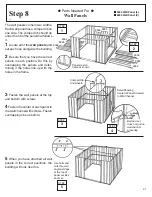
Страница 20: ...assemblies across the middle of the side panels using screws Fasten overlaps in rear corners with screws 5 Fasten the door track assembly holes on top across the top of the front wall panels using screws See the figure NOTE The wall channels behind the front wall panels will be installed in a later step Door Track Assembly 1 Rear Wall Angle Assembly 1 Side Wall Angle Assemblies 2 Rear Wall Channel...

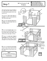
Страница 21: ... holes line up with the holes in the frame 3 Fasten the wall panels at the top and bottom with screws 4 Fasten the center of each panel to the wall channel with screws Fasten overlapping ribs as before 5 When you have attached all wall panels in the correct positions the building will look like this 21 STEP 1 9364 STEP 2 9364 STEP 4 Bolt and nut does not go thru wallchannel at overlap STEP 3 Crimp...

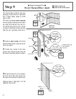
Страница 22: ...at this time 2 Fasten a door jamb to the front panel with two bolts nuts and acorn nuts as shown 3 Fasten the center of the door jamb to the front wall panel and the front wall channel with two screws 4Fastenthetopofthe doorjambto the door track with two screws Do the same for the bottom into frame Repeat steps 2 through 4 for the opposite door jamb 22 Acorn Nut Hex Nut 9900 F R O N T Screw Screw ...

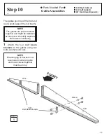
Страница 23: ...e them before continuing 1 Attach the four roof beam brackets to the gables using two bolts washers and nuts NOTE Mounting leg of bracket must face toward center of gable and holes closest together must be on top Parts Needed For Gable Assemblies Step 10 A23 6000 Right Gable 2 6001 Left Gable 2 5971 Roof Beam Bracket 4 STEP 1 5971 Roof Beam Brackets Washer 6001 6000 FRONT ...

Страница 24: ...rews Hint On the rear gable use a bolt and nut at the overlapping rear wall angle On the front gable leave out 2 screws closest to center gable leg 2 Join the left and right gables together with a gable brace using a bolt and nut in the bottom hole only 3 Repeat Steps 1 2 for the door track on the front of building except for the track supports fasten as shown STEP 3 Track Supports 6228 STEP 1 Gab...

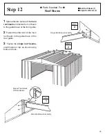
Страница 25: ...and fasten the roof beam to the gable brace of the front gable 2 Fasten the other end of the main roof beam to the gable brace of the rear gable 3 Fasten the single roof beams small holes on top as shown using bolts and nuts STEP 1 Spread Two Halves Of Roof Beams STEP 3 Single Roof Beam Assembly STEP 2 Main Roof Beam Assembly ...

Страница 26: ...oles will align NOTE If a Roof Beef Up Kit was purchased assemble prior to attaching the roof panels 1 Locate the roof panels by their numbers Note the sequence and position they are to be installed 2Positiontherightroofpanelatthe back right corner and fasten to the gable with 5 bolts and nuts and roof beams using 2 screws Do not fasten the lower end of the panel to the side wall angle at this tim...

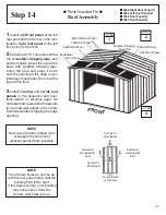
Страница 27: ...l 2 6529 Roof Panel 2 2Cut4short2 5 1cm stripsoffthe roll of weather stripping tape and put them aside Cover the joint at the peak with weather stripping tape Unroll the tape and press it down over the opening at the ridge as you install each roof panel Do not cut the tape at this time NOTE If roof beam holes do not line up with the roof panel holes shift the building from left to right If this do...

Страница 28: ...cm piece of weather stripping tape Do not fastentheendsoftheridgecapatthis time 2 Install the second ridge cap over lapping the first ridge cap while in stalling the remaining narrow roof panels Continue weather stripping the ridge 3 Fasten the lower end of the panels to the side wall angles using screws and washers Use bolts and nuts through wall angle overlaps at the bottom of the panel STEP 1 8...

Страница 29: ...de roof trim at the corner inward enough so the right and left roof trim caps fit onto right and left corners 3 Fasten the roof trim caps to the side trim using a screw 4 Fasten the roof panel ribs peak caps and ridge caps together using bolts and nuts 29 Step 16 A29 Parts Needed For RoofTrim 8485 Left Side Roof Trim 2 8836 Right Side Roof Trim 2 STEP 4 Peak Cap STEP 3 Tuck Flange Inward to Fit In...

Страница 30: ...a screw 3 Hold the vertical door brace against the center of the inside sur face of the door and turn the screw to hold the vertical door brace and door handle brace in place Fasten to door above and below center connection using 2 screws 4 Insert a second bolt in the door handle and tighten both bolts 5 Put a horizontal door brace onto the top edge and bottom edge and fasten with 1 bolt in the ce...

Страница 31: ... the door slides 3 Fasten the door to the door slides usingtwo 10Bx1 2 13mm screws per door slide NOTE The holes in the door slides allow you to adjust the doors Place the door in the middle holes 4 Repeat steps 1 through 3 for the left door Keep this Owner s Manual and Assembly Instructions for future reference STEP 2 HorizontalDoorBrace STEP 1 Gable STEP 3 10Bx1 2 13 mm Screw DoorSlide Adjustmen...

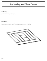
Страница 32: ...Anchoring Anchor your building at this time Floor Frame If you have purchased a Floor Frame Kit you need to install it at this time 32 Anchoring and Floor Frame UO32 ...

Страница 33: ...as it appears 1 Avoid nicking or scraping the coating surface inside and out 2 Use all the washers supplied In addition to pro tecting against weather infiltration the washers pro tect the metal from being scraped by the screws 3 Keep roof base perimeter and door tracks free of debris and leaves which may accumulate and retain moisture These can do double damage since they give off acid as they de...

Отзывы: