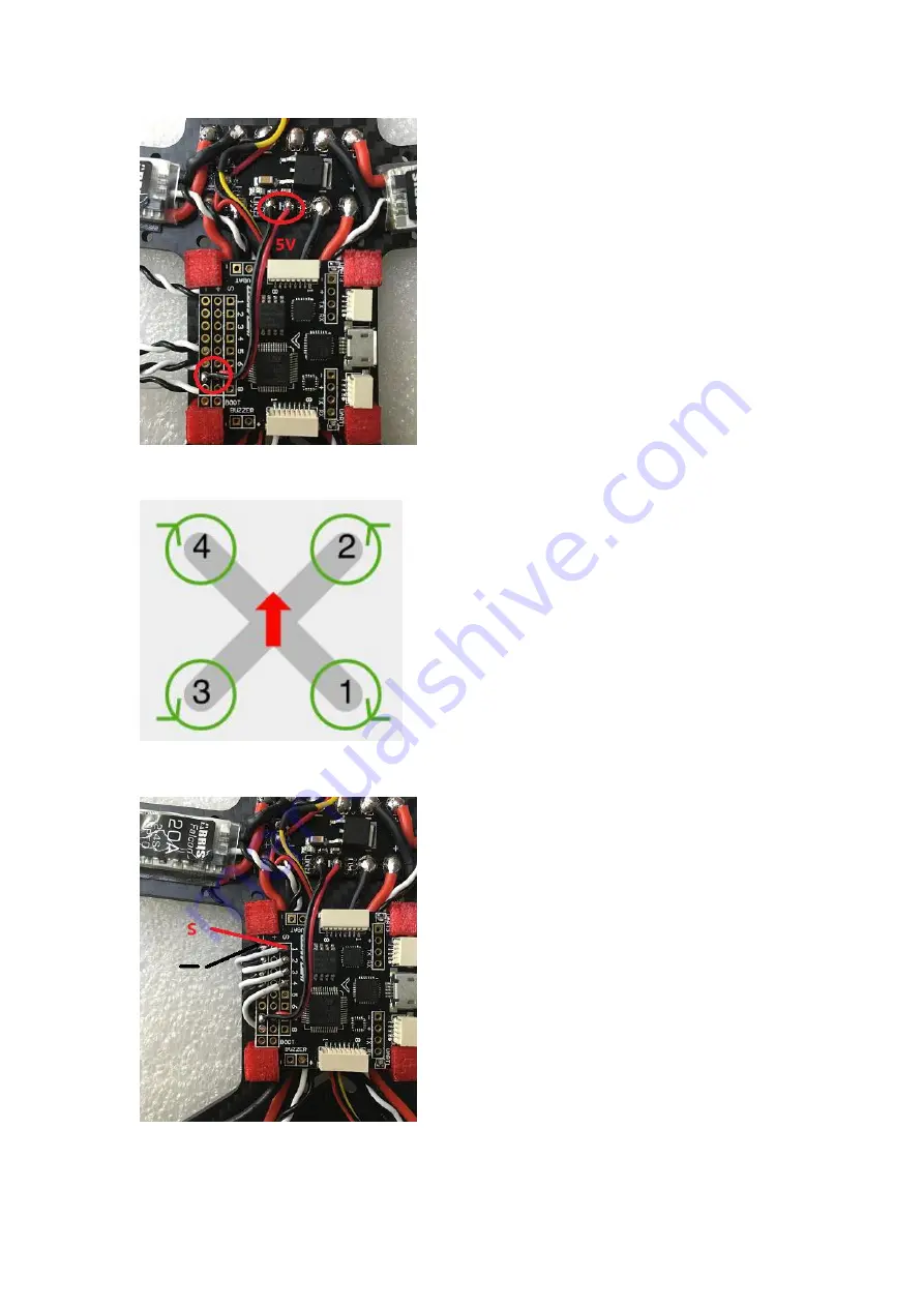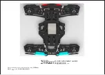
5.32. Solder the wires of brushless ESC. 1.2.3.4 label on the below diagram refers to positions of
the 4 ESCs, you need to solder them to the above corresponding positions.
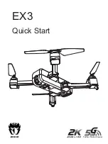
5.4. Solder the negative electrode (black wire) of F3 to “-” position on position and solder signal
wire (red) to “S” position. Here we use R6D receiver, which support PPM model.
5.5. Wrap the signal wire (red) with heat-shrinkable tube to avid short circuit.
5.6. Install the buzzer.
Содержание X180
Страница 15: ......


