background image


- 101 - 


TECHNICAL SPECIFICATIONS 

UPS Models 

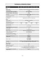
10 kVA 

12 kVA 

15 kVA 

20 kVA 

Input 


Nominal voltage 

380-400-415 Vac 3-phase with neutral (4 wire) / 220-230-240 Vac single phase 

Nominal frequency 

50-60Hz 

Accepted input voltage tolerance due to no 
intervention of the battery (referred to 400Vac) 

±

20% @ 100% load 

-40% +20% @50% load 

Accepted input frequency tolerance due to no 
intervention of the battery (referred to 50/60Hz) 

±

20% 

40-72Hz 

Technology 

High frequency IGBT with individual digital average current mode PFC control on 

each input phase 

Input current harmonic distortion 

THDi 

 3%


(8)


Input power factor 

0.99 

Power Walk-In 

Programmable from 5 to 30 sec. in 1 second steps 

Output 

Nominal voltage 

(1)


220/230/240 Vac single phase 

Nominal frequency 

(2)


50/60Hz 

Nominal apparent output power  

10kVA 

12kVA 

15kVA 

20kVA 

Nominal active output power  

8kW 

9.6kW 

12kW 

16kW 

Output power factor 

0.8 

Short circuit current 

1.5x In for t>500ms 

Precision of output voltage (referred to output 
voltage of 400Vac) 

±

 1% 

Static stability 

(3)


±

 0.5% 

Dynamic stability 

±

 3% resistive load

 (4)


EN62040 -3 performance class 1 distorting load 

Voltage harmonic distortion with linear and 
normalised distorting load 

1% with linear load 

3% with distorting load


Crest factor allowed with nominal load 

3:1 

Frequency precision in free running mode 

0.01% 

Inverter overloads @ PFout = 0.8 
(Resistive load)  

110% 10 min 

133% 1 min  
150% 5 sec 

>150% 0.5 sec  

Bypass overload 

110% Infinite 

133% 60 minutes 
150% 10 minutes 

>150% 2 sec 

Technology 

High frequency IGBT with digital multiprocessor (DSP+

μ

P), voltage/current 

based on signal processing techniques with feed forward 

Battery Charger 

Nominal voltage 

±

240Vdc 

Maximum recharge current 

(5)


6A 

Battery charger algorithm 

Two levels with temperature compensation 

Technology 

Analogue switching current mode under microprocessor control 

(PWM voltage and charge current adjustment) 

Input voltage tolerance for recharging at 
maximum current 

345-480Vac 


Содержание Flexus FM

Страница 1: ...THE SCIENCE OF CONTINUITY MANUALE D USO USER M A N U A L B E T R I E B S H A N D B U C H M A N U E L D UTILISATEUR M A N U A L D E USUARII...

Страница 2: ...manual contains detailed instructions on how to use and install the product For information on how to use your equipment to its full potential this manual should be kept close at hand beside the UPS...

Страница 3: ...RY BOX FROM THE PALLET 65 PRELIMINARY CHECK OF CONTENTS 66 INSTALLING THE UPS AND THE BATTERY BOX 66 STEPS TO BE TAKEN TO GAIN ACCESS TO THE TERMINALS OF THE UPS BATTERY BOX 66 ELECTRICAL CONNECTIONS...

Страница 4: ...5 MAINTENANCE BYPASS SWMB 85 REDUNDANT AUXILIARY POWER SUPPLY FOR AUTOMATIC BYPASS 86 PROGRAMMABLE AUXILIARY SOCKET POWER SHARE 86 POWER WALK IN 86 REDUCING THE LOAD TO 200V AND 208V 86 CONFIGURING TH...

Страница 5: ...Thanks to its new modern design the use of a large graphic display and above all the extra power provided by the battery charger up to 6A recharge the Flexus FM series represents a new reference stand...

Страница 6: ...Manual bypass switch Battery start button COLD START 1 0 main power switch Front door to open the door press and release the area marked X From left Input switch Separate bypass switch optional Outpu...

Страница 7: ...l OUTPUT Connection for remote maintenance bypass command Connection for external Battery Box temperature probe Connection for external synchronization signal Connection for R E P O Remote Emergency P...

Страница 8: ...communication cards RS232 communication port Powershare sockets max total 10A on two sockets USB communication port Powershare socket thermal protector manual reset Ventilation fans Contact holder fo...

Страница 9: ...er LED Battery low LED Battery power LED ECO mode LED Load on bypass LED Graphic display Stand by alarm LED F1 F2 F3 F4 FUNCTION KEYS The function of each key is indicated at the bottom of the display...

Страница 10: ...he battery voltage of the Battery Box corresponds to that supported by the UPS Additional Battery Boxes may be connected in a chain to obtain the desired autonomy time during a power failure This seri...

Страница 11: ...ONAL BATTERY CHARGERS ARE USED INSTEAD OF THE BATTERIES This series of UPS must be used together with an external Battery Box and is suitable for applications requiring long back up times NOTE A separ...

Страница 12: ...h 0 670 kW 580 kcal h 2290 B T U h 0 765 kW 660 kcal h 2610 B T U h 1 02 kW 880 kcal h 3480 B T U h Dissipated power with nominal distorting load pf 0 7 and with charged battery 0 49 kW 420 kcal h 16...

Страница 13: ...should not exceed 90 non condensing Check that the ambient temperature with the UPS running remains between 0 and 40 C The UPS may be operated with an ambient temperature of between 0 and 40 C The re...

Страница 14: ...door and remove the slides NOTE 2 The slides are fixed to the pallet by a screw marked C in the figure Remove the 4 brackets securing the UPS to the pallet the screws are marked A and B in the figures...

Страница 15: ...front of the equipment for it to be turned on off and maintenance operations to be performed on it 1 5 mt The rear part of the UPS should be set at least 30 cm from the wall to enable the air blown by...

Страница 16: ...otation must be respected Optional TRANSFORMER BOXES are available to convert the distribution system from 3 to 4 wires DIAGRAMS OF CONNECTIONS TO THE ELECTRICAL SYSTEM NOTE for the following diagrams...

Страница 17: ...8 UPS without any variation in neutral condition and with separate bypass input UPS with galvanic isolation and with separate bypass input UPS with galvanic isolation at output and separate bypass inp...

Страница 18: ...o the same potential If the two power supplies were different an isolation transformer would have to be used on one of the inputs UPS without any variation in neutral condition and with separate bypas...

Страница 19: ...ery chargers optional the maximum input current on lines L2 and L3 should be increased to 7A When operating off the bypass with a three phase connection all the output current is applied to L1 and Neu...

Страница 20: ...GF In Nominal current 2 DIFFERENTIAL In the standard version the neutral from the mains power is connected to the UPS output neutral and the neutral settings of the installation remain unchanged THE...

Страница 21: ...nal Battery Box is 3 metres Note the maximum cable size that can be inserted in the INPUT BYPASS and OUTPUT terminal boards is 25mm2 for cables with cable lugs and 35mm2 for rigid cables The maximum s...

Страница 22: ...AL Note connections to the BATTERY module are only required when the optional Battery Box is present CONNECTION OF UPS SINGLE PHASE INPUT The very first connection must be the protection conductor or...

Страница 23: ...lf powered with SELV type circuits No external power supply voltage is therefore required When it is closed normal condition a maximum current of 15mA is present EXTERNAL SYNC This non isolated input...

Страница 24: ...ass disconnecting switch If the UPS is fitted with an internal isolation transformer ensure compatibility between the remote maintenance bypass and the neutral arrangements DIAGRAM SHOWING REMOTE INST...

Страница 25: ...ns given in the UPS Internal Protections section NOTE For installation with single phase input use a bi polar disconnecting switch OUTPUT switch switch compliant with the indications given in the UPS...

Страница 26: ...e Battery Box are open Remove the terminal cover of the Battery Box see Opening the UPS and the Battery Box Connect the earth terminals of the UPS and the Battery Box using the yellow green wire of th...

Страница 27: ...panel of the UPS Installing and running UPSTools Follow the installation and operating instructions given in the software manual present in the UPSTools folder of the CD ROM Making the setting from t...

Страница 28: ...plied the internal temperature and the state of efficiency of the batteries The block diagram below shows each of the parts that make up the UPS Block diagram of the UPS IMPORTANT Our UPS are designed...

Страница 29: ...information as provided in the Connecting the Battery Box to the UPS paragraph this can lead to the battery fuses becoming damaged If this happens contact the customer services department immediately...

Страница 30: ...bypass option is present check which terminal board input and or bypass the error code shown on the display corresponds to see the Alarm Codes paragraph correct the position of the wires of the termi...

Страница 31: ...position Keep the Cold Start button situated behind the door pressed for about 5 sec The UPS will be started and the display turned on Press the button to gain access to the power on menu When prompte...

Страница 32: ...s containing all the data related to the menu chosen UPS STATUS ERRORS FAULTS Area indicating the operating status of the UPS The first line is always active and constantly shows the current status of...

Страница 33: ...84 DISPLAY MENUS...
Страница 34: ...f may result in injury to the operator and damage the equipment Below is a list of the operations to be performed in order to carry out maintenance work on the equipment without shutting off the power...

Страница 35: ...f battery charging or when an overload occurs Safety notes when the UPS is switched on if the output switch SWOUT is opened the Power share socket will remain connected to the mains If the manual bypa...

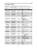
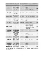
Страница 36: ...d Enabled Disabled CP Autonomy limitation Sets the maximum time of operation on battery power Disabled Disabled complete battery discharge 1 65000 in steps of 1 sec SW Battery low prealarm Sets the es...

Страница 37: ...vity Enabled High sensitivity Enabled Low sensitivity Disabled with input output synchronization Disabled without input output synchronization SW Inverter synchronization External Sync Selects the sou...

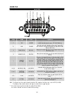
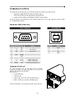
Страница 38: ...USB CONNECTORS RS232 CONNECTOR USB CONNECTOR 1 2 3 4 PIN NAME TYPE SIGNAL PIN SIGNAL 1 IN 1 VBUS 2 TX OUT Serial line TX 2 D 3 RX IN Serial line RX 3 D 4 4 GND 5 GND POWER 6 OUT 7 8 15V POWER Isolate...

Страница 39: ...hen the mains voltage is present the UPS resumes operation from the inverter If the jumper is removed when there is no mains voltage present the UPS resumes operation from the battery 4 5 12 BATTERY L...

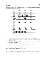
Страница 40: ...ted when the UPS switches to bypass to compensate for the surge current due to the activation of a distorting load Sound C The signal is emitted when the UPS switches to battery operation before the b...

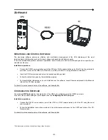
Страница 41: ...llow the instructions given by the installation program For more detailed information on how to install and use the software consult the manual present in the Manuals folder of the CD Rom provided To...

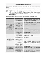
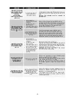
Страница 42: ...CH LOCATED BEHIND THE DOOR IN 0 POSITION Set the switch to 1 THE SWIN SWITCH LOCATED BEHIND THE DOOR IS OPEN Close the switch MAINS POWER FAILURE BLACKOUT Check that mains power is restored and if nec...

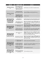
Страница 43: ...DISPLAY SHOWS ONE OR MORE OF THE FOLLOWING CODES F09 F10 PHASE 1 HAS A MUCH LOWER VOLTAGE THAN THE OTHER TWO PHASES Open the SWIN start up the UPS using the batteries wait until the sequence ends and...

Страница 44: ...THE BATTERIES ARE DISCHARGED THE UPS WAITS UNTIL THE BATTERY VOLTAGE RISES ABOVE THE ESTABLISHED THRESHOLD VALUE Wait for the batteries to recharge or manually force start up from the START UP menu T...

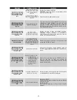
Страница 45: ...PLAY SHOWS ONE OR MORE OF THE FOLLOWING CODES F37 L37 ENVIRONMENTAL TEMPERATURE HIGHER THAN 40 C SOURCES OF HEAT NEAR THE UPS AIR VENTS OBSTRUCTED OR TOO NEAR THE WALL MALFUNCTION OF THE TEMPERATURE S...

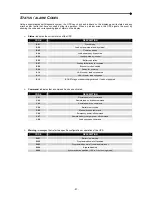
Страница 46: ...recharge S08 Economy mode enabled S09 Ready for power on S10 UPS locked load not powered S11 UPS locked load on bypass S12 BOOST stage or battery charger locked load not powered Command indicates that...

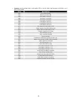
Страница 47: ...tside tolerance limits A18 Voltage on bypass line out of range A19 Overcurrent peak on output A22 Load user defined threshold A25 Output isolator open A26 Positive branch batteries missing or battery...

Страница 48: ...ositive branch capacitors failed F10 Precharge of negative branch capacitors failed F11 BOOST stage anomaly F14 Sine wave of inverter distorted F17 Inverter stage anomaly F19 Positive battery overvolt...

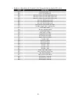
Страница 49: ...ervoltage positive L07 BOOST stage overvoltage negative L08 BOOST stage undervoltage positive L09 BOOST stage undervoltage negative L10 Static bypass switch fault L11 output undervoltage L14 inverter...

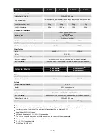
Страница 50: ...r factor 0 8 Short circuit current 1 5x In for t 500ms Precision of output voltage referred to output voltage of 400Vac 1 Static stability 3 0 5 Dynamic stability 3 resistive load 4 EN62040 3 performa...

Страница 51: ...x Models ET06P480A5 6 ET06V480A0 6 ET06P480M5 6 ET06V480M0 6 Battery Nominal voltage per branch 240Vdc Number of batteries V 40 12 80 12 Various Environmental temperature 7 0 40 C Humidity 95 non cond...

Отзывы: