


507640-05
Page 15 of 25
Issue 2245
must be sized to carry minimum circuit ampacity marked
on the unit. Use copper conductors only. Each unit must be
wired with a separate branch circuit and be properly fused.
NOTE:
An optional bottom-entry power kit is available for
these units. See the kit instructions for proper installation
details.
208/230 Line Voltage Wiring
If 208 Volt is supplied, transformer connection
must be changed
SINGLE PHASE POWER SUPPL
Y
GROUND
LUG
CONTACTOR
FIELD-SUPPLIED FUSED
OR CIRCUIT BREAKER
DISCONNECT
Figure 5.
When connecting electrical power and control wiring
to the unit, waterproof type connectors must be used
so that water or moisture cannot be drawn into the unit
during normal operation.
CAUTION
Thermostat
This dual fuel system requires the use of a field supplied
dual fuel thermostat. The thermostat must be capable
of monitoring outdoor ambient temperature, control two
stages of Cool (Y1, Y2), control two stages of Heat Pump
(Y1, Y2) and control the changeover from Heat Pump (Y)
to Gas Heat (W).
The room thermostat should be located on an inside
wall where it will not be subject to drafts, sun exposure,
or heat from electrical fixtures or appliances. Follow the
manufacturer’s instructions enclosed with thermostat for
general installation procedure. Color-coded insulated wires
(#18 AWG) should be used to connect the thermostat to
the unit.
Compressor
Units are shipped with compressor mountings factory-
adjusted and ready for operation.
Do not loosen compressor mounting bolts.
CAUTION
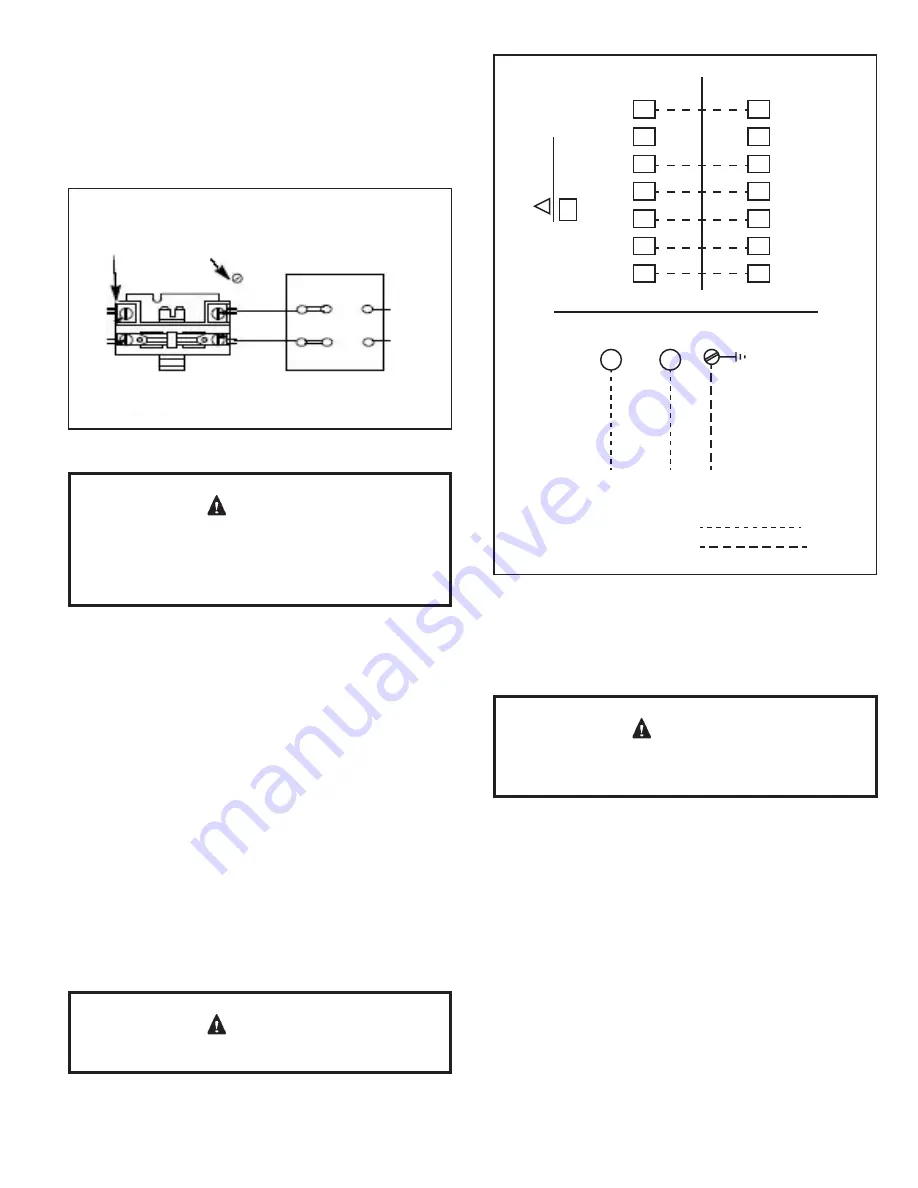
Figure 6. Typical Wiring Connections
R
G
W
O
Y2
Y1
C
R
G
W
O
Y2
Y1
C
THERMOSTAT
OUTDOOR UNIT
Red
Blue
Yellow
Yellow w/
Blue Stripe
Orange
White
Green
!
CAUTION
required by the indoor thermostat. Refer to th
e
thermostat installation instructions
.
Do not connec
t
connections except whe
n
C
SINGLE PHASE
L2
L1
GROUND
SCREW
POWER WIRING
208/230-1-60
(75° MIN. WIRE)
POWER WIRING
24V CONTROL WIRING
(NEC CLASS 2)
Gas Heating Start-Up
For Your Safety Read Before Lighting
Furnace is equipped with a direct ignition control. Do
not attempt to manually light the burners.
CAUTION
Pre-Start Check List
Complete the following checks before starting the unit:
1. Check the type of gas being supplied. Be sure it is the
same as listed on the unit nameplate.
2. Make sure that the vent cover has been properly
installed.
To Light Main Burners:
1.
Turn off electrical power to unit.
2. Turn the thermostat to lowest setting.
3. Slide the gas valve switch to the “ON” position (see
Figure 7).
4. Turn on electrical power to the unit.


