Armstrong Air Conditioning 4SHP16LT Series Скачать руководство пользователя страница 12

Page 12

# 48478A006

START-UP

1. Rotate fan to check for frozen bearings or binding.

2. Inspect all factory and field-installed wiring for loose

connections.

3. After evacuation is complete, open liquid line and

suction line service valves to release refrigerant
charge (contained in outdoor unit) into system.

4. Replace the stem caps and secure finger tight, then

tighten an additional 1/6 of a turn.

5. Check voltage supply at the disconnect switch. The

voltage must be within the range listed on the unit
nameplate. If not, do not start equipment until the
power company has been consulted and the voltage
condition corrected.

6. Set thermostat for cooling demand, turn on power to

indoor blower, and close the outdoor unit disconnect
switch to start the unit.

7. Recheck unit voltage with unit running. Power must be

within range shown on unit nameplate.

Refrigerant Charging

This system is charged with R410A refrigerant which
operates at much higher pressures than R22. The liquid line
drier provided with the unit is approved for use with R410A.
Do not replace it with one designed for use with R22. 

This

unit is NOT approved for use with coils which use
capillary tubes as a refrigerant metering device.

R410A refrigerant cylinders are rose colored. Refriger-
ant should be added through the suction valve in the
liquid state.

Certain R410A cylinders are identified as being
equipped with a dip tube. These allow liquid refriger-
ant to be drawn from the bottom of the cylinder
without inverting the cylinder. Do not turn this type of
cylinder upside down to draw refrigerant.

Units are factory charged with the amount of R410A
refrigerant indicated on the unit rating plate. This charge is
based on a matching indoor coil and outdoor coil with 15'
line set. For varying lengths of line set, refer to Table 4 for

If unit is equipped with a crankcase heater, it
should be energized 24 hours before unit
start-up to prevent compressor damage as a
result of slugging.

  CAUTION

Mineral oils are not compatible with R410A. If
oil must be added, it must be a polyol ester oil.

  IMPORTANT

refrigerant charge adjustment. A blank space is provided
on the unit rating plate to list the actual field charge.

If the system is void of refrigerant, clean the system using
the procedure described below.

1. Use dry nitrogen to pressurize the system and check

for leaks. Repair leaks, if possible.

2. Evacuate the system to remove as much of the

moisture as possible.

3. Use dry nitrogen to break the vacuum.

4. Evacuate the system again.

5. Weigh the appropriate amount of R410A refrigerant

(listed on unit nameplate) into the system.

6. Monitor the system to determine the amount of

moisture remaining in the oil. Use a test kit to verify
that the moisture content is within the kit’s dry color
range. It may be necessary to replace the filter drier
several times to achieve the required dryness level.

If system dryness is not verified, the compressor
will fail in the future.

The outdoor unit should be charged during warm weather.
However, applications arise in which charging must occur
in the colder months. The method of charging is deter-
mined by the 

outdoor ambient temperature

.

Measure the liquid line temperature and the outdoor
ambient temperature as outlined below:

1. Connect the manifold gauge set to the service valve

ports as follows (see Figure 12):

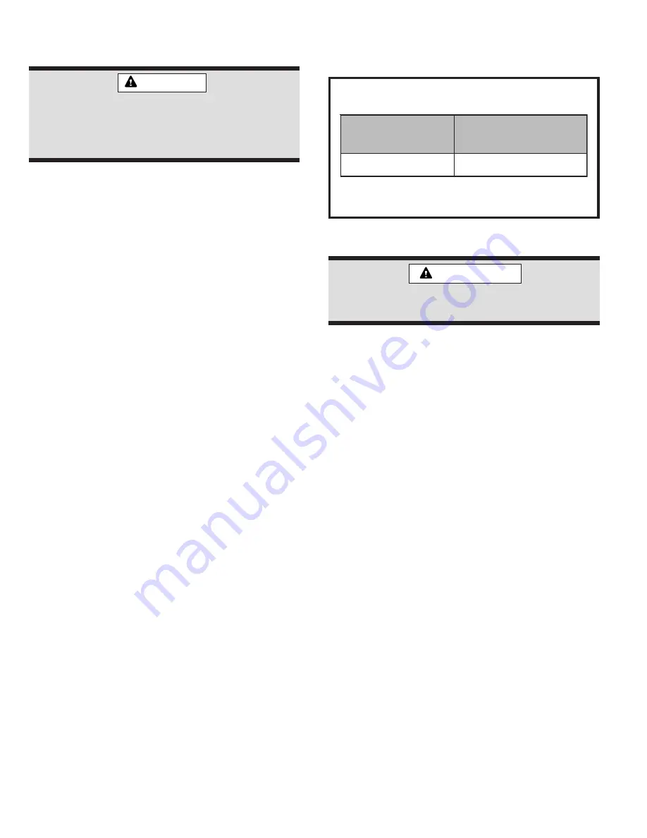
Refrigerant Charge Adjustment

* If line length is 

greater than 15 ft.

, add this amount.

If line length is 

less than 15 ft.

, remove this amount.

Table 4

t

e

S

e

n

i

L

d

i

u

q

i

L

r

e

t

e

m

a

i

D

t

s

u

j

d

a

.

t

f

5

r

e

p

.

z

O

*

t

e

s

e

n

i

l

.

t

f

5

1

m

o

r

f

.

n

i

8

/

3

.

t

f

5

r

e

p

.

z

o

3

Содержание 4SHP16LT Series

Страница 1: ...mote power supplies before installing or servicing any portion of the system Failure to disconnect power supplies can result in property damage personal injury or death WARNING The equipment covered i...

Страница 2: ...his product has been designed and manu factured to meet ENERGY STAR criteria for energy effi ciency when matched with appropriate coil components However proper refrigerant charge and proper air flow...

Страница 3: ...of the control box Connect conduit to the control box using a proper conduit fitting Units are approved for use only with copper conductors 24V Class II circuit connections are made in the low voltag...

Страница 4: ...0 6 3 8 3 8 3 8 3 8 3 2 1 0 0 0 2 4 8 3 8 3 8 3 2 1 2 1 0 0 0 8 4 8 3 8 3 8 3 2 1 2 1 0 0 0 0 6 8 3 8 3 8 3 2 1 2 1 Figure 3 Thermostat Designations Some connections may not apply Refer to specific t...

Страница 5: ...how to install line sets on horizontal runs Figure 6 shows how to make a transition from horizontal to vertical Figure 7 shows how to install line sets on vertical runs Brazing Connection Procedure 1...

Страница 6: ...lex Liquid Line Strap Liquid Line to Vapor Line Figure 5 To hang line set from joist or rafter use either metal strapping material or anchored heavy nylon wire ties Strapping Material around vapor lin...

Страница 7: ...an insulator preventing proper heat transfer It can also clog the thermal expansion valve reducing system performance and capacity Failure to properly flush system as explained in these instructions w...

Страница 8: ...vices are not approved for use with R410A refrigerant and may prevent proper flushing Use a field provided fitting to reconnect the lines 5 Remove the pressure tap valve cores from the 4SHP16LT unit s...

Страница 9: ...ine to the equalizer port on the suction line and tighten to 8 ft lbs Table 3 TXV Data l e d o M t r a P r e b m u N 0 3 4 2 T L 6 1 P H S 4 1 0 V X T 4 H 6 3 T L 6 1 P H S 4 2 0 V X T 4 H T L 6 1 P H...

Страница 10: ...inger tight then tighten an additional 1 6 turn To Close Liquid or Suction Line Service Valve 1 Remove the stem cap with an adjustable wrench 2 Use a service wrench with a hex head extension to turn t...

Страница 11: ...e vacuum pump with vacuum gauge to the center port of the manifold gauge set 4 Open both manifold valves and start vacuum pump 5 Evacuate the line set and indoor unit to a minimum of 500 microns or lo...

Страница 12: ...ching indoor coil and outdoor coil with 15 line set For varying lengths of line set refer to Table 4 for If unit is equipped with a crankcase heater it should be energized 24 hours before unit start u...

Страница 13: ...to use Proceed with the appropriate charging method Charge Using Weigh In Method If the system is void of refrigerant or if the outdoor ambient temperature is cool first locate and repair any leaks t...

Страница 14: ...2 2 1 4 0 2 1 7 7 1 4 1 2 1 2 3 2 4 2 2 1 8 8 2 4 3 2 1 5 4 3 4 4 2 1 2 0 4 4 5 2 1 9 5 4 4 6 2 1 8 1 5 4 7 2 1 6 7 5 4 8 2 1 5 3 6 4 9 2 1 5 9 6 4 0 3 1 6 5 7 4 1 3 1 6 1 8 4 2 3 1 8 7 8 4 3 3 1 0 4...

Страница 15: ...1 5 2 4 2 4 1 F 5 1 1 5 8 4 4 5 1 9 8 4 1 5 1 1 9 4 1 5 1 6 8 4 6 4 1 1 g n i t a e H t s y t i c a p a C w o L e g a t S F 0 4 7 3 3 3 9 8 2 3 8 9 9 6 3 5 7 1 5 3 3 6 F 0 5 2 2 3 7 1 1 3 3 3 8 1 1 6...

Страница 16: ...ch temperature Approach Values for TXV Systems Approach value is the liquid line temperature minus the outdoor ambient temperature 1 F NOTE For best results use the same digital thermometer to check b...

Страница 17: ...Strip Connections High Pressure Switch Defrost Thermostat Low Pressure Switch Reversing Valve Compressor Delay Pins Test Pins K1 Relay K2 Relay FAN DS1 L 24V P2 P5 O OUT DF Y1 OUT HI PS U1 U2 DS2 K3 R...

Страница 18: ...The delay helps to protect the compressor from short cycling in case the power to the unit is interrupted or a pressure switch opens The delay is bypassed by placing the timer select jumper across th...

Страница 19: ...l a n i m r e t e l u d o m t a t n e s e r p s i e g a t l o v y l p p u S P I R T d e R d n a m e d t a t s o m r e h T t n e s e r p s i 1 Y l a n g i s r o s s e r p m o c e h t t u b g n i n n u...

Страница 20: ...i d n i w r o s s e r p m o C 7 e c n a t s i s e r g n i d n i w r o t o m r o s s e r p m o c k c e h C T R E L A w o l l e Y h s a l F 6 e d o C t i u c r i C t r a t S n e p O n u r n i y l n o t...

Страница 21: ...o t d e t c e n n o c s i l a n i m r e t Y y f i r e V f f o n e h w C A V 5 0 w o l e b s l l a f s l i o c D E L T R E L A d n a D E L P I R T r e h t e g o t g n i h s a l f C A V 8 2 9 1 h t i w...

Страница 22: ...pet urine cottonwood seeds etc Visually inspect the refrigerant lines and coils for leaks Check wiring for loose connections Check voltage at the indoor and outdoor units with units operating Check a...

Страница 23: ...lean the outdoor coil with an unpressurized water hose to remove surface contaminants and debris It may be necessary to flush the outdoor coil more frequently if it is exposed to substances which are...

Страница 24: ...and provides temporary heat supplied by the auxiliary heat Indicating Light Most heat pump thermostats have an amber light which indicates when the heat pump is operating in the emer gency heat mode...

Страница 25: ...Fan ______________ Maximum Fuse or Circuit Breaker________________________ Electrical Connections Tight Indoor Filter Clean Supply Voltage Unit Off ________________ Indoor Blower RPM _____________ S P...

Страница 26: ...SE INJURY OR DEATH UNIT MUST BE GROUNDED IN ACCORDANCE WITH NATIONAL AND LOCAL CODES LINE VOLTAGE FACTORY INSTALLED LINE VOLTAGE FIELD INSTALLED 24 VOLT FACTORY INSTALLED CLASS II VOLTAGE FIELD INSTAL...

Страница 27: ...ly to you Only Warranty This written Limited Warranty is the only warranty made by the warrantor this warranty is in lieu of and excludes all other warranties express or implied The warrantor does not...

Отзывы: