3. Connect the Cables
NOTE
: Technical specifications are subject to change without prior notice.
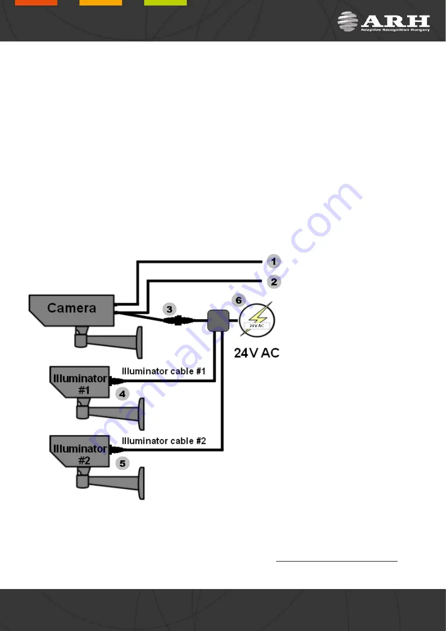
The camera is pre-assembled with three cables. The first cable (
1
) is responsible for communication via TCP/IP, the
second (
2
) one is for user trigger and serial connections and the third cable (
3
) is for power supply (
6
) and
illuminator communication (
4
and
5
).
RJ45: with e.g. inline coupler
User I/O and Power&Illuminator: with e.g. junction box
IMPORTANT NOTICE! For cabling use quality, outdoor-certified cables!
Improper cabling causes warranty to void! Water may enter into the camera inside through loose cable
ends. Use smooth circular cables only (6-8mm diameter).
NOTE
: Junction box is included in the package only if the camera has been purchased with illuminators.
The camera is pre-assembled with cables according to the followings:
1. Ethernet
2. User I/O
1. Opto Out G (–)
2. Serial RX
3. Serial TX
4. Opto In S (+)
5. Opto In G (–)
6. Opto Out S (+)
7. (Green/Yellow) Serial GND
3. Power&Illuminator
1. AC
2. Illuminator Control 1
3. Illuminator Control 2
4. Illuminator Control Out +
5. Illuminator Control 3
6. AC
7. (Green/Yellow) Illuminator
Control Out -
4. Illuminator connector
5. Illuminator connector
6. Power
AC
AC
IMPORTANT
: SEAL THE UNUSED CABLE ENDINGS (END SLEEVES) BEFORE CONNECTING TO POWER IN
ORDER TO AVOID DAMAGES DUE TO SHORT CIRCUIT!
Page 7/17
Page 7/17
Page 7/17
Page 7/17
FreewayCAM Install Guide


