9
P-51 MUSTANG
Item code: BH140
.
Instruction Manual
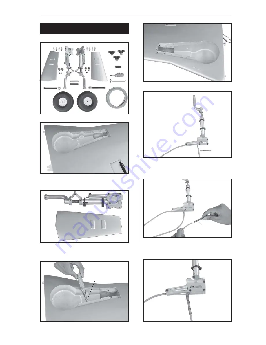
PARTS REQUIRED
INSTALLING AIR RETRACTABLE
LANDING GEAR.
5x45mm.
3x15mm.
spring
Drill a hole 3mm diameter
Страница 1: ...Instruction Manual book SPECIFICATION Wingspan 2 050mm 80 71 in Length 1 840 mm 72 41 in Weight 6 8kg 14 96 Lbs Radio 07 channels Servo 09 servos Engine O S GT 33 CC gas Made in Vietnam ITEM CODE BH 140 ...
Страница 2: ... T pins Thread lock Paper towels Some more parts HARDWAREPACK Cowling Landing gear To avoid scratching your new airplane do not unwrap the pieces until they are needed for assembly Cover your workbench with an old towel or brown paper both to protect the air craft and to protect the table Keep a couple of jars or bowls handy to hold the small parts af ter you open the bag PARTS LISTING FUSELAGE AS...
Страница 3: ...he area and rub down with a soft cloth Wing warp Hold the panel twisted gently in the opposite direction to the warp and apply warm air to remove the creases from the covering Caution do not heat the film more than is absolutely necessary If the air or the iron is too hot the film may melt and holes may be formed This model is highly pre fabricated and can be built in a very short time However the...
Страница 4: ...ain gear 2 Door mounting wheel 4 Bomb tray 5 Wheels 6 Antenna 3 Plastic bomb REPLACEMENT SMALL PARTS 3x20mm F2 Aluminium tube Horizontal stabilizer E Rudder F1 Aluminium tube wing dihedral brace G Decal sheet A Cowling B Wing panel B1 B2 C Fuselage D Horizontal stabilizer D1 D2 K K Pilot G ...
Страница 5: ...OS 2 Using a modeling knife remove the cov ering at possition show below Aileron Remove covering Servo tray Secure Top side 10 Fuel tank 8 Air tank 11 3 way connector 9 Air line sets 12 Valve one way 13 Valve control 15 Battery tray 16 Tail gear set 14 Spinner bottom side Flap Aileron Servo tray Servo tray 17 Gun set for wing 7 Plastic parts for bottom fuselage ...
Страница 6: ...RON CONTROL HORN thread Electric wire Secure A B Epoxy PLUS glue Aileron control horn INSTALLING THE AILERON LINKAGES 60mm 3x10mm 3 Using the thread as a guide and using masking tape tape the servo lead to the end of the thread carefully pull the thread out When you have pulled the servo lead out re move the masking tape and the servo lead from the thread 4 Drill 1 6mm pilot holes through the bloc...
Страница 7: ...7 P 51 MUSTANG Item code BH140 Instruction Manual Repeat the procedure for the other wing half 2x10mm Secure Bottom side servo tray Secure II FLAP 1 INSTALLING THE FLAP SERVO Flap Bottom side ...
Страница 8: ... as same as picture below Control horn Flap 2 INSTALLING THE FLAP CONTROL HORN Repeat the procedure for the other wing half A B Epoxy PLUS glue Control horn of the flap Installing the flap linkages as pictures below Secure Bottom side 3 INSTALLING THE FLAP LINKAGES 60mm 3x10mm ...
Страница 9: ...9 P 51 MUSTANG Item code BH140 Instruction Manual PARTS REQUIRED INSTALLING AIR RETRACTABLE LANDING GEAR 5x45mm 5x45mm 3x15mm spring spring Drill a hole 3mm diameter ...
Страница 10: ...10 P 51 MUSTANG Item code BH140 Instruction Manual Secure 3x15mm 5x45mm ...
Страница 11: ...11 P 51 MUSTANG Item code BH140 Instruction Manual Secure 3x10mm 3x6mm Secure 3x6mm Drill a hole 2mm Secure 3x10mm ...
Страница 12: ...12 P 51 MUSTANG Item code BH140 Instruction Manual Bottom side Flap Aileron Installing plastic parts for bomb wing Secure Secure Secure 3x 15mm 3x20mm ...
Страница 13: ...res below Drill a hole 6mm diameter Front view 1 Install one adjustable metal connector through the third hole out from the center of one servo arm enlarge the hole in the servo arm using a 2mm drill bit to accommodate the servo connector Remove the excess mate rial from the arm INSTALLING THE ENGINE 5x70mm INSTALLING THE THROTTLE PUSHROD Secure ...
Страница 14: ...gth of silicon fuel line the length of silicon fuel line is calculated by how the weighted clunk should rest about 8mm away from the rear of the tank and move freely inside the tank Connect one end of the line to the weighted clunk and the other end to the nylon pick up tube in the stop per 3 Carefully bend the second nylon tube up at a 45 degree angle using a cigarette lighter This tube will be t...
Страница 15: ... tank in place apply a bead of silicon sealer to the forward area of the tank where it exits the fuselage behind the engine mounting box and to the rear of the tank at the forward bulkhead Do not secure the tank into place perma nently until after balancing the airplane You may need to remove the tank to mount the battery in the fuel tank compartment 7 Using a modeling knife cut 3 lengths of fuel ...
Страница 16: ...age COWLING 2 While keeping the back edge of the cowl flush with the marks align the front of the cowl with the crankshaft of the engine The front of the cowl should be positioned so the crankshaft is in nearly the middle of the cowl opening Hold the cowl firmly in place using pieces of masking tape Fuel tank Pushrod Choke Left side Pushrod Choke Pushrod Choke Top side ...
Страница 17: ...1 MUSTANG Item code BH140 Instruction Manual Bottom side 3 Slide the cowl back over the engine and secure it in place using four wood screws Trim and cut 3x 12mm Bottom side Secure Secure Right side Left side ...
Страница 18: ...ode BH140 Instruction Manual INSTALLING THE SPINNER Install the spinner backplate propeller and spinner cone The spinner cone is held in place using two 3mm x 8mm machine screws Front view Aluminium 10mm 5x50mm Secure Secure ...
Страница 19: ...o Test fit the servo into the servo tray 2 Mount the servo to the tray using the mounting screws provided with your radio system 12 mm 300 mm Aluminium Elevator servo Elevator servo Elevator servo HORIZONTAL STABILIZER Horizontal stabilizer installation See picture below Right side PUSH Left horizontal stabilizer Right horizontal stabilizer Bottom side ...
Страница 20: ... the way of aileron pushrod ELEVATOR PUSHROD INSTALLATION Elevator control horn install as same as the way of aileron control horn Please see pic tures below ELEVATOR CONTROL HORN INSTALLATION Bottom side Bottom side 4x15mm Secure A B Epoxy PLus glue Elevator control horn M2 M2 lock nut ...
Страница 21: ...truction Manual E l e v a t o r pushrod Bottom side Elevator pushrod Elevator pushrod bend 90 degree Cut E l e v a t o r pushrod Rudder servo install as same as method of elevator servo See picture below Rudder servo RUDDER INSTALLATION ...
Страница 22: ...nstruction Manual Rudder control horn install as same as the way of aileron control horn Please see pic tures below Control horn of Rudder RUDDER CONTROL HORN INSTALLA TION Rudderservo A B Epoxy PLus glue Aluminium Rudder Aluminium Cut ...
Страница 23: ...nstruction Manual 1 Rudder push pull system install as same as picture below RUDDER CABLE INSTALLATION A B Epoxy PLus glue Control horn Rudder Bottom side Rudder cable Rudder cable Elevator pushrod Rudder cable Bottom side Rudder cable ...
Страница 24: ... wheel assembly in place on the plywood plate The pivot point of the tail wheel wire should be even with the rud der hinge line and the tail wheel bracket should be centered on the plywood plate MOUNTING THE TAIL WHEEL BRACKET 3x15mm Open 3x15mm Secure Secure 3x10mm ...
Страница 25: ...STANG Item code BH140 Instruction Manual Plastic parts of elevator pushrod and rudder cable valve control servo INSTALLING SERVO USING FOR VALVE CONTROL bottom side Top side C A glue Cut Push pull cable tail gear ...
Страница 26: ...Instruction Manual Valve control servo Air supply Valveoneway 3wayconnector Air tank 3wayconnector 3wayconnector Right main gear wing Left main gear wing Valve control Valve control Valve control Secure INSTALLATION AIR TANK Air tank ...
Страница 27: ...27 P 51 MUSTANG Item code BH140 Instruction Manual BH 140 ...
Страница 28: ...m in place 3 Position the battery pack and receiver behind the fuel tank Use two tie wraps to hold the battery and receiver securely in place as pictures below Do not permanently secure the receiver and battery until after balancing the model 4 Using a 2mm drill bit drill a hole through the side of the fuselage near the receiver for the antenna to exit 1 Cut out the switch hole using a modeling kn...
Страница 29: ...uminium tube 25 mm 762 mm WING ATTACHMENT Battery of engine Battery of receiver Receiver Test fit the aluminium tube dihedral brace into each wing haft The brace should slide in easily If not use 220 grit sand around the edges and ends of the brace until it fits prop erly 2 Attach the aluminium tube into the fuselage ...
Страница 30: ...30 P 51 MUSTANG Item code BH140 Instruction Manual 3 Insert two wing panels as pictures below Right wing Left wing Secure Secure ...
Страница 31: ...code BH140 Instruction Manual INSTALLING COCKPIT FUSELAGE See picture below A B Epoxy PLUS glue C A glue C A glue See picture wing attach to fuselage Installing the fuselage hatch as same as pic ture below Insert and secure ...
Страница 32: ...32 P 51 MUSTANG Item code BH140 Instruction Manual Antenna gun set for wing C A glue Left side Front view Right side Front view Installing plastic bottom fuselage bottom side A B EPOXY PLUS GLUE Secure ...
Страница 33: ...oint With the wing attached to the fuselage all parts of the model installed ready to fly and empty fuel tanks hold the model at the marked balance point with the stabilizer level Accurately mark the balance point on the top of the wing on both sides of the fuselage The balance point is located 181mm back from the leading edge This is the balance point at which your model should balance for your f...
Страница 34: ...re your first day of fly ing 2 Check every bolt and every glue joint in your plane to ensure that everything is tight and well bonded 3 Double check the balance of the airplane 4 Check the control surface 5 Check the receiver antenna It should be fully extended and not coiled up inside the fuselage 6 Properly balance the propeller PRE FLIGHT CHECK 35mm 20mm 30mm 30mm 15 mm 15mm 20mm ...