Arecont Vision MegaView 2 AV10225PMIR Скачать руководство пользователя страница 1


Arecont Vision MegaView

®

 2 Installation Manual


Installation Manual 


Wide Angle Models: 

AV1225PMIR-S   

AV2225PMIR           AV2225PMIR-S 

AV2225PMIR-A       AV2225PMIR-SA 

AV2226PMIR           AV2226PMIR-S 

AV3225PMIR           AV3225PMIR-S 

AV3226PMIR           AV3226PMIR-S 

AV3226PMIR-A       AV3226PMIR-SA 

AV5225PMIR           AV5225PMIR-S 

AV5225PMIR-A       AV5225PMIR-SA 

AV10225PMIR         AV10225PMIR-S 
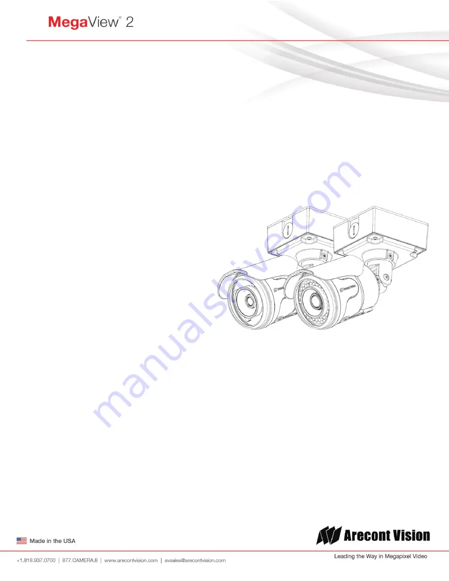
 

Telephoto Models: 

AV2225PMTIR        AV2225PMTIR-S 

AV2226PMTIR        AV2226PMTIR-S 

AV3225PMTIR        AV3225PMTIR-S 

AV3226PMTIR        AV3226PMTIR-S 

AV5225PMTIR        AV5225PMTIR-S 

AV10225PMTIR      AV10225PMTIR-S 


Telephoto Model                   Wide Angle Models 

Содержание MegaView 2 AV10225PMIR

Страница 1: ...PMIR S AV3225PMIR AV3225PMIR S AV3226PMIR AV3226PMIR S AV3226PMIR A AV3226PMIR SA AV5225PMIR AV5225PMIR S AV5225PMIR A AV5225PMIR SA AV10225PMIR AV10225PMIR S Telephoto Models AV2225PMTIR AV2225PMTIR S AV2226PMTIR AV2226PMTIR S AV3225PMTIR AV3225PMTIR S AV3226PMTIR AV3226PMTIR S AV5225PMTIR AV5225PMTIR S AV10225PMTIR AV10225PMTIR S Telephoto Model Wide Angle Models ...

Страница 2: ...Replacing the IR LED board 9 Camera Discovery 10 Web Interface Quick Guide 14 SD Card Functionality 22 Electrical Box Adapter SV EBA Installation Instructions Sold Separately 25 Pole Mount Adapter AV PMA Installation Instructions Sold Separately 26 Corner Mount Adapter AV CRMA Installation Instructions Sold Separately 27 Installation Best Practices 30 LED Indicators Camera Signal 31 Support 32 Mou...

Страница 3: ...box adapter D Mounting Template for MegaView 2 Camera E CD with AV100 software and user manuals license key required for recording F Security L key G Pack of four 4 screws and four 4 anchors NOTE Anchors and screws are good to be used for concrete wall block and red bricks NOTE Screws by themselves can be used in wood H Rubber plug I Pack of four 4 machine screws 8 32 Phillips Pan Head Image 1 D A...

Страница 4: ...misuse abuse improper storage testing or connection or unauthorized repair or iv is no longer covered under the Warranty Period ARECONT VISION MAKE NO WARRANTIES OR CONDITIONS EXPRESS IMPLIED STATUTORY OR OTHERWISE OTHER THAN THE EXPRESS LIMITED WARRANTIES MADE BY ARECONT VISION ABOVE AND ARECONT VISION HEREBY SPECIFICALLY DISCLAIMS ALL OTHER EXPRESS STATUTORY AND IMPLIED WARRANTIES AND CONDITIONS...

Страница 5: ...n or water pipe seal tape to make sure no water leakage between conduit pipe and junction box adapter 5 Run Ethernet cable and other cables if necessary through the Junction Box Adapter and connect to Megaview 2 pigtail cable as shown in Image 8 6 Add provided rubber plug Image1 H on the bracket to ensure a water tight installation for outdoor applications as shown in Image 3 7 Organize pigtail ca...

Страница 6: ...stant NOTE 2 Bracket with 3 axes enables easy installation in any location including 360 camera body rotation 90 tilt 360 bracket rotation Image 7 Image 7 NOTE 3 MegaView 2 is a total PoE class 0 solution to power the camera IR illuminator and fan Fan is always on NOTE 4 To use the external power 12 48VDC or 24VAC power on camera connect external power with pigtail cable connector Image 8 NOTE 5 O...

Страница 7: ...cteristics Min Max Input voltage V measured between and terminals ON 2 9 6 3 OFF 0 1 3 OFF 0 1 Table 1 NOTE 3 The digital input is electrically isolated from the rest of the camera s electrical circuitry via general purpose photo couplers The input is additionally protected with a serial 250 Ohm resistor and a debouncing circuit Duration of any input signal should be at least 5 ms to comply with t...

Страница 8: ...2 Use Phillips screwdriver to unscrew four screws on the lid and take off the lid as shown in Image 10 3 Push SD card into SD card slot or take SD card out from SD card slot as shown in Image 11 Note For more SD card information please refer to SD Card Functionality Image 9 Image 10 Image 11 Image 12 NOTE Please Insert SD card in the correct orientation as shown on Image 12 ...

Страница 9: ...mage 13 2 Use Phillips screwdriver to remove IR LED board Image 14 3 To replace IR LED board unplug cable and replace new IR LED board Image 14 1 NOTE 48pcs IR LED board for wide angle MV2 part number M000094 34 4pcs IR LED board for tele photo part number M000094 38 Image 13 Image 14 Image 14 1 ...

Страница 10: ... and chose Open This will start the installation and is followed by the installation welcome screen Click next and follow the AV200 Setup Wizard to install the AV200 3 Adding Cameras with System Setup Wizard After the AV200 is installed the first time it is launched the System Setup Wizard will be started Anytime you wish to re run the setup wizard in the future you can access it from your desktop...

Страница 11: ...t selected by default No changes will be made to any cameras not selected see next wizard page Click Next to continue The following screen will display a list of cameras discovered on the network The Refresh button provides an option to make sure all cameras are found or to rediscover cameras that were connected after wizard started If Refresh is selected the wizard will display the discovery scre...

Страница 12: ...ignifying the camera as inaccessible No camera IP addresses are changed at this stage To apply an IP change to all selected cameras check the radio button labeled Force IP renewal If changes are made to the address the screen will be followed by an individual confirmation of the IP address change and the title of each camera found on the network Individual confirmation screens for each camera can ...

Страница 13: ... camera to its previous IP address To skip any remaining individual camera information pages check the radio button for do not show info for individual cameras Select Next to continue Following the camera discovery process a summary of all cameras set up in the system will be displayed Check the cameras listed on this screen to confirm that all cameras connected to the network have been discovered...

Страница 14: ...ra image and works in conjunction with the exposure controls to maintain the image brightness Sharpness controls sharpness and edge definition of the image Setting this to higher levels may make overall image to appear a bit softer while causing lines and edges in the image to look smoother Saturation controls the color saturation of the image Rotate Image allows image to be digitally rotated 0 90...

Страница 15: ...ues as illumination levels rise Toggle Guard should be adjusted to prevent the mode from toggling between Night and Day modes in areas where transitional lighting exists in the scene Enable P Iris this button enables the P Iris control function on the camera Note If Enable P Iris is unchecked the iris will be fully open to the maximum It may result in less sharpness and artificial color under stro...

Страница 16: ...splay of video in the browser using this compression 4 H 264 Menu RTSP Unicast port this numeric field allows configuration of the application port for RTSP Unicast video streams Default is 554 valid values that can be set are 1 65535 Variable Bitrate Control when this radio button is selected the camera will maintain the bit rate based on the Quality setting and rate limit configured There may be...

Страница 17: ...onstant bit rate control will set a hard limit for the bit rate Image compression will be set to whatever value achieves the configured bit rate This method of bit rate control can achieve a more consistent overall bit rate Image quality will be dependent on camera resolution illumination and scene content based on the constant control limit configured i Bitrate this numeric field allows setting t...

Страница 18: ...Mask the sub net of the local network can be manually configured in this field Default Gateway the gateway IP address for the local network can be manually configured in this field DHCP Fixed Selection these radio buttons allow configuring the camera as either Fixed IP manually configured or DHCP auto addressed from local DHCP server when selected Miscellaneous settings allow assignment of a camer...

Страница 19: ...e Detail will set the size of the object being detected within the zone level sets the duration that movement must be maintained to trigger motion detection Lower settings can increase false motion alarms caused by image noise higher settings will require more movement to trigger a motion event Motion Sensitivity determines the sensitivity to sudden overall brightness changes in the image This set...

Страница 20: ...nstructions on this feature Playback SDcard video allows the user to choose the specific time of video to playback SD Card Recording Continuous Recording allows the user enable continuously recording Stop Continuous Recording AND Enable Event triggered Recording allows the user to enable events recording when network failure motion alarm or I O alarm triggered NOTE if the continuous recording is d...

Страница 21: ...In and connect an active speaker with a built in amplifier via the in line jack as shown in Image 8 if needed 2 Choose H 264 over RTP UDP as shown on Image 15 1 and check Enable Microphone then click Preview and Apply buttons as shown on Image 15 2 NOTE Audio only works in H 264 RTP UDP streaming Image 15 1 Image 15 2 ...

Страница 22: ...Typical lower grade SD cards are meant for multimedia applications and will at times have questionable quality and reliability 2 Recording to the SD card is FIFO first in first out The oldest first entry is deleted first as new storage requirements arise There is no indication when this will happen Storage time is dependent on a variety of factors such as SD card size and camera FPS 3 SD Recording...

Страница 23: ... continuously recording Stop Continuous Recording AND Enable Event triggered Recording to enable events recording for network failure motion alarm and or I O alarm trigger iv You will see the Start and End times once the camera starts recording see image below The start time represents the beginning time of the oldest recording v To playback recorded video 1 Input the date and time of the desired ...

Страница 24: ...e SD card drop down menu Choose Continuous Recording OR Event triggered Recording to enable events recording for network failure motion alarm or I O alarm iii To launch the SD card playback window click on the SD card icon iv Set play range to full span will set the playback range to the maximum available on the SD card v Set playback range will allow the user to input the playback date and time m...

Страница 25: ...eeded Common electrical box such as single gang box double gang box or square electrical boxes shown in Image 17 1 4 1 Remove the electrical box adapter and hardware from the box 2 Attach the wall mount bracket to the electrical box adapter 3 Attach adapter to electrical box Image 17 1 Single gang box Image 17 2 Double gang box Image 17 3 Square box Image 17 4 Square box MegaView 2 Bracket holes A...

Страница 26: ... Remove the conduit plug on Junction box adapter and connect NPT Conduit to Junction Box Adapter shown in Image 19 1 NOTE Use silicon or water pipe seal tape to make sure no water leakage between conduit pipe and junction box adapter 4 Run Ethernet Cable and other cables if necessary through the Junction Box Adapter and connect to MegaView 2 pigtail cable 5 Attach MegaView 2 bracket to Pole Mount ...

Страница 27: ...Remove the conduit plug on Junction box adapter and connect NPT Conduit to Junction Box Adapter shown in Image 22 1 NOTE Use silicon or water pipe seal tape to make sure no water leakage between conduit pipe and junction box adapter 4 Run Ethernet Cable and other cables if necessary through the Junction Box Adapter and connect to Megaview 2 pigtail cable 5 Attach MegaView 2 bracket to Corner Mount...

Страница 28: ...o avoid water leakage on a surface wall as shown in Image 25 NOTE Adding water seal tape on the thread of NPT pipe to avoid water leakage Important Note How to correctly install MegaView 2 on a surface wall How to correctly install MegaDome 2 on a ROUGH surface wall Image 25 Water seal tape MegaView 2 Recommended Image 24 Recommended NPT Conduit NPT Conduit Junction Box Adapter NOTE Tighten NPT pl...

Страница 29: ...it to Junction Box Adapter as shown on Image 27 or without tightening NPT plugs as shown on Image 28 may result in water leakage Not Recommended Without connecting NPT Conduit Image 26 Image 27 NOTE Water damage from improper installation is not covered by the warranty Junction Box Adapter Not Recommended Not Recommended Junction Box Adapter MegaView 2 NPT Conduit Without tightening NPT plugs Cond...

Страница 30: ...tion of conduit hole is at the lower side forming a drip loop below the camera using galvanized or flex conduit and appropriate fittings Connect NPT conduit pipe to junction box adapter Yes Tighten all camera screws and NPT plugs Caulk the perimeter of the mounting area Conduct periodic inspections of the installation Rust on the metal parts or screws may result in damage to camera End Installatio...

Страница 31: ... see the LED indicators open the plug on the camera body as shown in Image 37 Image 27 LED Status Description Yellow Flashing Link has been established Solid Normal Operation None No connection Green Flashing Camera has been accessed Normal operation Solid N A None No Connection Plug ...

Страница 32: ... the camera webpage Upgrade to the latest firmware by visiting ArecontVision com Isolate the camera on a dedicated network and test with AV100 or AV200 Swap the troubled camera with a known good camera to see if the problem follows the camera or stays at the location 3 Contact Arecont Vision Technical Support one of three ways 1 Online Portal Support ArecontVision com 2 Phone 1 818 937 0700 option...

Страница 33: ...Arecont Vision MegaView 2 Installation Manual Page 33 support arecontvision com Mounting Template Junction Box Adapter Mounting Template ...

Отзывы: