Arecont Vision MegaDome 2 AV10255AMIR Скачать руководство пользователя страница 6

Arecont Vision MegaDome

®

 2 Installation Manual 


Page | 6       [email protected] 


Install MegaDome

®

 2 Camera 


Mounting the Camera: 

 
1. 

Remove the camera and hardware from 
the box. 
 

2. 

Using the mounting template, prepare the 
mounting surface for camera installation.  
NOTE: the 19.5mm diameter hole on the 
Mounting template is where the Ethernet 
cable will be exiting the MegaDome®2 
align accordingly.  If using the side conduit 
hole, please see step 4 following. 
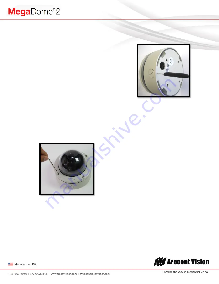
 

3. 

Using Security L-key, loosen the four (4) 
screws securing the dome cover (Image 2).  
Remove the vandal resistant dome cover.  
NOTE: Do not remove the screws from the 
dome cover. 


Image 2 

4. 

If you are using the side conduit 
opening, remove the conduit plug by 
first removing the socket set screw 
using the provided double-sided hex 
key (Image 3). 


Image 3 

Note: Make sure that you install the rubber 
gasket on the bottom of the camera to form 
a weather tight seal with the mount 
surface.  

5. 

Run the Ethernet cable through the gasket 
and the hole on the bottom of the camera 
(Image 4) or run the cable through the side 
conduit and plug it into the RJ45 port.  
NOTE: If the camera will be powered via 
PoE, please skip to step 6. 

6. 

If the camera will be powered by an AC or 
DC power supply, run the supplied power 
cable through the gasket and the hole on 
the bottom of the camera or run the cable 
through the side conduit and connect it to 
its respective connector inside the camera 
(Image 3).   


NOTE: Make sure that your installation of 
wires complies with Electrical Code of the 
local government where the camera is 
installed and that no bare wires are 
exposed.  

Содержание MegaDome 2 AV10255AMIR

Страница 1: ...V3256PMIR A AV2255AM AV5255AM AV2255AM A AV5255AM A AV2255AM H AV5255AM H AV2255AM AH AV5255AM AH AV2255AMIR AV5255AMIR AV2255AMIR A AV5255AMIR A AV2255AMIR H AV5255AMIR H AV2255AMIR AH AV5255AMIR AH...

Страница 2: ...ntvision com Telephoto Models AV2255PMTIR H AV2256PMTIR AV3255PMTIR H AV3256PMTIR AV5255PMTIR H AV10255PMTIR H Manual Lens Models AV1255DN AV1255DN H AV2255DN AV2255DN H AV2256DN AV3255DN AV3255DN H A...

Страница 3: ...Installation Instructions Sold Separately 13 Junction Box Adapter SV JBA Installation Instruction Sold Separately 14 Electrical Box Adapter SV EBA Installation Instructions Sold Separately 18 Pole Mou...

Страница 4: ...AV100 software and user manuals License Key Required for Recording D AC DC power cable E I O cable F Pack of four 4 screws and four 4 anchors NOTE Anchors and screws are good to be used for concrete...

Страница 5: ...isuse abuse improper storage testing or connection or unauthorized repair or iv is no longer covered under the Warranty Period ARECONT VISION MAKE NO WARRANTIES OR CONDITIONS EXPRESS IMPLIED STATUTORY...

Страница 6: ...lug by first removing the socket set screw using the provided double sided hex key Image 3 Image 3 Note Make sure that you install the rubber gasket on the bottom of the camera to form a weather tight...

Страница 7: ...lt use a 1 Phillips screwdriver to loosen the screw on the side of the plastic lens bracket 1 4 turn Image 5 CAUTION Do not remove the screw 10 Adjust lens tilt as required and tighten the screw 11 To...

Страница 8: ...m focus and iris as needed Securing the Vandal Dome Cover 16 Adjust black liner position to avoid blocking IR light if equipped or the lens as shown in Image 7 17 Remove the protective film from the c...

Страница 9: ...C 14 F to 50 C 122 F 20 To adjust focus or zoom in AV200 open the camera interface and click the Zoom focus tab as shown in image 8 Image 8 21 To create focus area Region of Interest by drawing a rec...

Страница 10: ...n 1 NOTE 2 If the Enable Auto Focus after zoom option is checked as shown in image 8 the focus will automatically be adjusted when zoom is changed 28 Set up a focus area if necessary by drawing a rect...

Страница 11: ...32 To manually focus click the 20 5 1 20 5 1 buttons to fine tune the focus Image 13 Adjusting P Iris Note If Enable P Iris is unchecked the iris will be fully open to the maximum It may result in les...

Страница 12: ...dapter SV JBA to avoid water leakage risk on ROUGH surface wall surface as shown in Image 15 Image 15 Inappropriate Installation Attaching the MegaDome 2 directly onto a ROUGH wall surface may result...

Страница 13: ...Phillips head screwdriver Image 17 1 Remove the wall mount and hardware from the box Image 18 2 Using the mounting template prepare the mounting surface 3 Attach wall mount to the wall using screws or...

Страница 14: ...d screwdriver G Wall Mount MD WMT H NPT Conduit if necessary Image 19 1 Remove junction box adapter and hardware from the box Image 20 2 Remove the conduit plug by first removing the socket set screw...

Страница 15: ...re from the box Image 22 Image 23 8 Using the mounting template prepare the mounting surface for camera installation 9 Place small gasket onto pendant mount shown in image 22 10 Attach the top shield...

Страница 16: ...1 NPT coupling E 1 NPT flange F 2 Phillips head screwdriver Image 24 1 Remove the wall mount cap from the box 2 Assemble the wall mount cap 1 coupling 1 pipe nipple and 1 flange as a pendant Mount sho...

Страница 17: ...e from the box 2 Attach the dome to the flush mount adapter as shown in Image 27 Please reference Mounting the Camera if needed 3 Using the mounting template cut a hole in surface for mounting 4 Inser...

Страница 18: ...box such as single gang box double gang box or square electrical boxes shown in Image 30 1 4 1 Remove the electrical box adapter and hardware from the box 2 Attach the wall mount bracket to the elect...

Страница 19: ...e from the box 2 Install the compression fittings to pole mount adapter as shown in Image 32 3 Attach MegaDome wall mount MD WMT2 to pole mount adapter as shown in Image 33 4 Run the Ethernet cable an...

Страница 20: ...gs to corner mount adapter as shown in Image 35 3 Attach wall mount adapter to corner mount adapter and attach the wall mount cap as shown in Image 36 Image 35 Image 36 4 Run the Ethernet cable and ou...

Страница 21: ...Connect the heater cable to the connector on PCB as shown in Image 39 Red is positive cable NOTE 1 MegaDome 2 Heater MD2 HK uses 2 28 watts which is different from the MegaDome Heater MD 1HK is 10 wa...

Страница 22: ...ectrical Characteristics Min Max Input voltage V ON 2 9 6 3 measured between and terminals OFF 0 1 3 Output current mA ON 50 measured between and terminals Applied Voltage Rage 0 80V OFF 0 1 Table 1 I...

Страница 23: ...e hole in the bottom of the camera and connect them to the connectors on the circuit board as shown in Image 43 Image 43 D Connect a mono analog microphone to MICIN Microphone In connect the line in s...

Страница 24: ...24 support arecontvision com LED Indicators Camera Signal LED Status Description Yellow Flashing Link has been established Solid Normal Operation None No connection Green Flashing Camera has been acce...

Страница 25: ...the camera webpage Upgrade to the latest firmware by visiting ArecontVision com Isolate the camera on a dedicated network and test with AV100 or AV200 Swap the troubled camera with a known good camera...

Страница 26: ...Arecont Vision MegaDome 2 Installation Manual Page 26 support arecontvision com Mounting Template...

Отзывы: