Arecont Vision AV10355PMIR-SH Скачать руководство пользователя страница 18


Installation Manual 


Page | 18       [email protected] 


+1.818.937.0700    877.CAMERA.8    www.arecontvision.com    [email protected] 

Mega

Dome

®

 G3


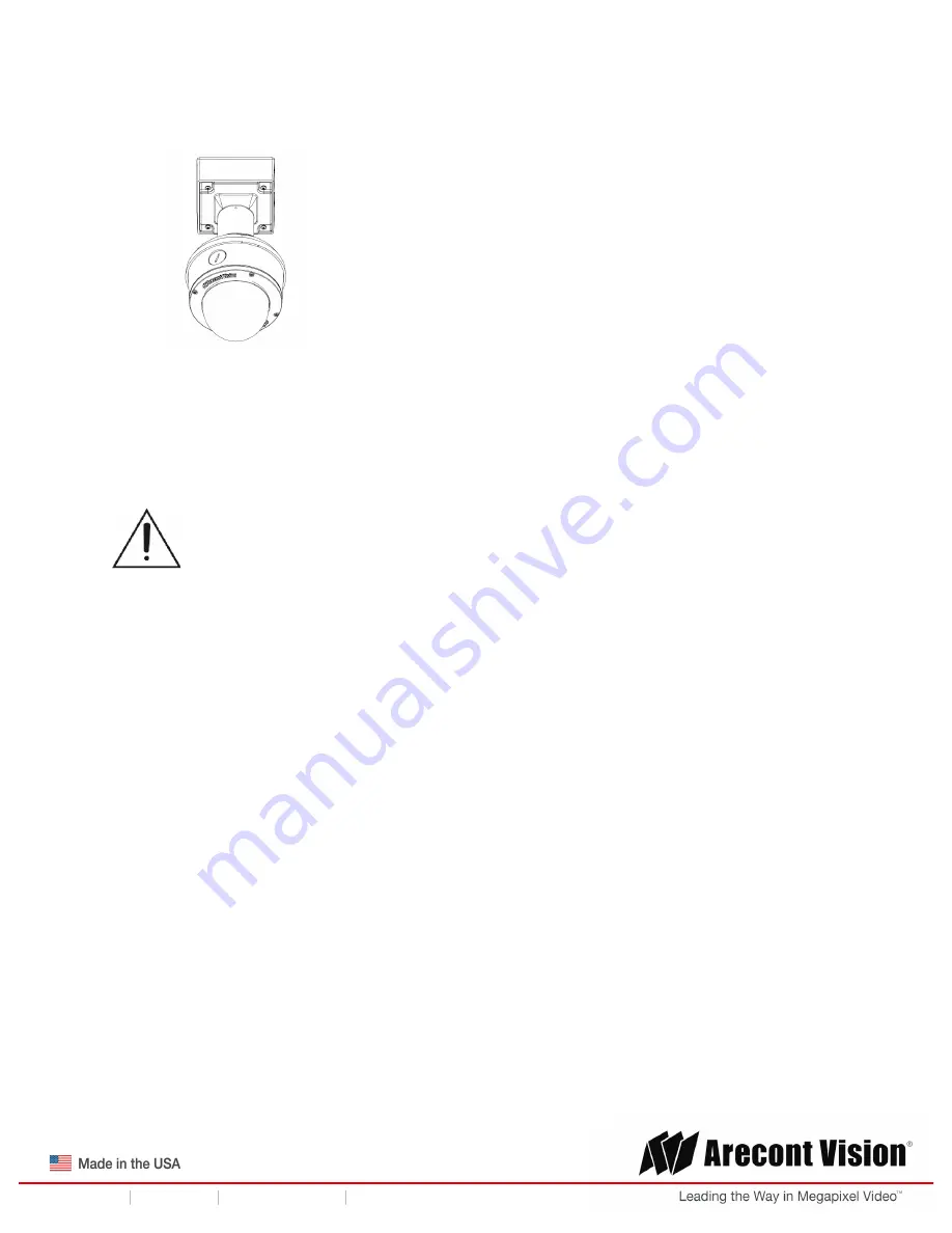
9.  Attach the Dome Cover to the MegaDome

®

 G3 camera and fasten securely four captive 

screws as shown in Figure 6. 


Figure 6 
 

NOTE: When attaching the Dome Cover, make sure the IR foam on the lens not block the field 
of view.  


10. To configure the camera, reference the camera discovery, set-up and configuration section. 


CAUTION! 

The captive screws must be used to properly secure the dome cover and 

camera housing. Failure to use the captive fastener may result in serious injury. When 
mounting the dome cover to the camera housing, ensure that the gasket is properly seated 
and not folded. Failure to do so may result in water and dust ingress. Water damage from 
improper installation is not covered by the warranty! 


Содержание AV10355PMIR-SH

Страница 1: ...355PMIR S 1080p AV2355PMIR SH AV2356PMIR S AV2355PMIR SAH AV2355PMTIR SH AV2356PMTIR S 3 Megapixel AV3355PMIR SH AV3356PMIR S AV3356PMIR SA AV3355PMTIR SH AV3356PMTIR S 5 Megapixel AV5355PMIR SH AV5355PMIR SAH AV5355PMTIR SH 10 Megapixel AV10355PMIR SH AV10355PMTIR SH ...

Страница 2: ... Mount 10 Wall Mount 13 Pendant Mount 16 Pole Mount 19 Corner Mount 21 Electrical Box Adapter 23 Adjusting the Pan Tilt and Focus 24 Auxiliary I O Functions 26 Camera Power Up 28 SD Card Set up 30 SD Card Tab 33 SD Card Setup via AV200 34 Camera Discovery Setup and Configuration 35 Network Protocols 35 General Remote Focus 36 Refined Remote Focus 37 AV IP Utility Focus Tab 39 Mounting Templates 40...

Страница 3: ...th all local codes and authorities having jurisdiction Wiring should be UL Listed and or Recognized wire suitable for the application 3 Always use hardware e g screws anchors bolts locking nuts etc which are compatible with mounting surface and of sufficient length and construction to insure a secure mount Package Contents This equipment should be unpacked and handled with care The original packag...

Страница 4: ...mera 2 1x Dome Cover 3 1x Mounting Plate 4 1x Grommet with Through Hole 5 1x Grommet without Through Hole 6 1x Insertion Tool 7 4x 6 32 1 0 Wood Metal Sheet Screw 8 4x 6 32 1 0 Drywall Masonry Mounting Anchors 9 4x 8 32 0 5 Machine Screw 10 1x Security L key 11 1x Set Screw L key 12 1x Mounting Template 13 1x Magnetic core 1x I O cable 1x AC DC auxiliary power cable 1x CD with Manual and Software ...

Страница 5: ...ted to unusual stress neglect misuse abuse improper storage testing or connection or unauthorized repair or iv is no longer covered under the Warranty Period ARECONT VISION MAKE NO WARRANTIES OR CONDITIONS EXPRESS IMPLIED STATUTORY OR OTHERWISE OTHER THAN THE EXPRESS LIMITED WARRANTIES MADE BY ARECONT VISION ABOVE AND ARECONT VISION HEREBY SPECIFICALLY DISCLAIMS ALL OTHER EXPRESS STATUTORY AND IMP...

Страница 6: ...art Noise Adaptation and Processing technology to reduce bandwidth without impacting image quality Together with an IR corrected motorized P iris wide angle or telephoto varifocal lens remote focus and remote zoom make MegaDome G3 easy to install and manage The installer friendly housing is IP66 environmental rated and IK 10 impact resistant MegaDome G3 is feature loaded and select models include ...

Страница 7: ... to loosen the four 4 screws securing the dome cover 3 Remove the dome cover and protective foam Do not remove screws from the dome cover The MegaDome G3 camera has been designed to provide installers with flexible mounting options such as ceilings walls poles or corners NOTE When mounting the camera outdoors or in a wet environment use of supplied grommet is recommended Ensure the grommet properl...

Страница 8: ...oper compatible mounting parts prior to starting your installation Pendant mount Reference Pendant Mount Components Required 1 Pendant mount AV PMJB with integrated junction box 2 MegaDome G3 camera 3 MD CAP mounting cap Wall mount Reference Wall Mount Components Required 1 Wall mount AV WMJB with integrated junction box 2 MegaDome G3 camera 3 MD CAP mounting cap ...

Страница 9: ... cap 3 MegaDome G3 camera 4 AV PMA pole mount adapter Corner mount Reference Corner Mount Components Required 1 Wall mount AV WMJB with integrated junction box 2 MD CAP mounting cap 3 MegaDome G3 camera 4 AV CRMA corner mount adapter 4 Use the Arecont Vision software AV IP Utility located on the CD or available for download at our website www arecontvision com for camera discovery and setup see In...

Страница 10: ...rs and screws provided to prepare the mounting provisions for the camera installation 2 Use the supplied security L key to loosen the four 4 tamper resistant screws securing the dome cover as shown in Figure 1 Do not remove screws from the dome cover Figure 1 3 Remove the protective foam and discard 4 Install four supplied dry wall anchors using the supplied mounting template 5 Align four supplied...

Страница 11: ...met is properly seated flush with the camera housing 7 Align the hole on MegaDome G3 camera with the hole on mounting plate and install the grommet on camera housing as shown in Figure 4 Figure 4 NOTE If using the side connection of the NPT port you need to install the supplied grommet without a through hole on the camera housing and remove the cap covering the side entrance otherwise leave the ca...

Страница 12: ...e sure the IR foam on the lens not block the field of view 10 To configure the camera reference the camera discovery set up and configuration section CAUTION The captive screws must be used to properly secure the dome cover and camera housing Failure to use the captive fastener may result in serious injury When mounting the dome cover to the camera housing ensure that the gasket is properly seated...

Страница 13: ...g provisions for the camera installation 2 Connect wall mount cap and wall mount as shown in Figure 1 Figure 1 Attach wall mount cap to the wall mount NOTE The thread size for Top shield pendant pole and mount is 1 5 NPT 3 Attach the wall mount to the wall using the four drywall screws provided or any optional hardware suitable for the mounting surface 4 Run the Ethernet Cable and outside power ca...

Страница 14: ...ol as shown in Figure 3 Figure 3 NOTE When mounting the camera outdoors or in a wet environment use of supplied grommet is recommended Ensure the grommet is properly seated flush with the camera housing 7 Align the hole on MegaDome G3 camera with the hole on mounting plate and install the grommet on camera housing as shown in Figure 4 Figure 4 8 Fasten securely four captive screws as shown in Figu...

Страница 15: ...on the lens not block the field of view 10 To configure the camera reference the camera discovery set up and configuration section CAUTION The captive screws must be used to properly secure the dome cover and camera housing Failure to use the captive fastener may result in serious injury When mounting the dome cover to the camera housing ensure that the gasket is properly seated and not folded Fai...

Страница 16: ... provisions for the camera installation 2 Connect top shield pendant pole and mount together as shown in Figure 1 Figure 1 Attach the mount cap and pendant mount NOTE The thread size of top shield pendant pole and mount is 1 5 NPT 3 Attach the pendant mount to the ceiling using the four wood screws provided or any optional hardware suitable for the mounting surface 4 Run the Ethernet Cable and out...

Страница 17: ...ol as shown in Figure 3 Figure 3 NOTE When mounting the camera outdoors or in a wet environment use of supplied grommet is recommended Ensure the grommet is properly seated flush with the camera housing 7 Align the hole on MegaDome G3 camera with the hole on mounting plate and install the grommet on camera housing as shown in Figure 4 Figure 4 8 Fasten securely four captive screws as shown in Figu...

Страница 18: ...on the lens not block the field of view 10 To configure the camera reference the camera discovery set up and configuration section CAUTION The captive screws must be used to properly secure the dome cover and camera housing Failure to use the captive fastener may result in serious injury When mounting the dome cover to the camera housing ensure that the gasket is properly seated and not folded Fai...

Страница 19: ...Attach the Junction Box Adapter to the Pole Mount Adapter as shown in Figure 1 4 Remove the conduit plug on the junction box adapter and connect NPT conduit to the junction box adapter Figure 1 Figure 1 Attach conduit to AV JBA junction box adapter Reference Description 1 Remove conduit plug 2 Connect NPT conduit to junction box adapter ensure use of water seal tape NOTE Use silicon or water pipe ...

Страница 20: ...ount Adapter to the pole and tighten the compression screws as shown in Figure 2 8 To attach the camera to the Wall Mount Adapter AV WMJB reference the Installation and Wall Mount section 9 To configure the camera reference the camera discovery set up and configuration section CAUTION The captive screws must be used to properly secure the dome cover and camera housing Failure to use the captive fa...

Страница 21: ...Corner Mount Adapter as shown in Figure 1 4 Remove the conduit plug on the junction box adapter and connect NPT conduit to the junction box adapter as shown in Figure 1 Figure 1 Attach conduit to SV JBA junction box adapter Reference Description 1 Remove conduit plug 2 Connect NPT conduit to junction box adapter ensure use of water seal tape NOTE Use silicon or water pipe seal tape to make sure no...

Страница 22: ...r other hardware attach the Corner Mount Adapter to an exterior 90 degree corner wall 8 To attach the camera to the Wall Mount Adapter AV WMJB reference the Installation and Wall Mount section 9 To configure the camera reference the camera discovery set up and configuration section CAUTION The captive screws must be used to properly secure the dome cover and camera housing Failure to use the capti...

Страница 23: ...tach the camera to a common single double or square electrical box 1 Using the supplied machine screws match the mounting holes on the mounting plate with the threaded holes on the electrical box Ensure every threaded hole is matched with a mounting hole 2 Attach the mounting plate to the user supplied electrical box as shown in Figure 1 Figure 1 Attach the mounting plate to common electrical box ...

Страница 24: ...cus 3 Remove the shroud from the camera gimbal and then loose two Philips head screws and loose one set screw with the supplied set screw L key and then adjust the pan and tilt to obtain the desired field of view as shown in Figure 1 NOTE Do not remove the screws Figure 1 Loose camera head to adjust the field of view 4 Lock the camera head in place by fastening securely two Philips head screws and...

Страница 25: ...77 CAMERA 8 www arecontvision com avsales arecontvision com MegaDome G3 NOTE Make sure align locking features of the shroud with mating parts on the camera gimbal as shown in Figure 3 Figure 3 6 To adjust the zoom and focus see the Remote Zoom Focus Section of this manual ...

Страница 26: ...tics Electrical Characteristics MIN MAX Input Voltage V Measured between and terminals ON 3 5 6 3 OFF 0 1 3 Output Current mA Measured between and terminals Applied Voltage Range 0 80V ON 50 OFF 0 1 Table 1 NOTE The digital input is electrically isolated from the rest of the camera s electrical circuitry via general purpose photo couplers The input is additionally protected with a serial 250 Ohm r...

Страница 27: ...ual Page 27 support arecontvision com 1 818 937 0700 877 CAMERA 8 www arecontvision com avsales arecontvision com MegaDome G3 Digital I O Orange Digital OUT Yellow Digital OUT White Digital IN Black Digital IN Table 2 ...

Страница 28: ...itch using an Ethernet cable as shown in the image below Reference Description 1 PoE Connector 2 If the camera is powered by an outside power supply 12 48 VDC or 24VAC connect the power cable 3 Connect the PoE switch to your computer s network port using an Ethernet cable Auxiliary Power If the camera is powered by a separate outside DC or AC power source run the supplied power cable through the a...

Страница 29: ...ts are properly sealed to prevent ingress of water NOTE A yellow LED on the rear of the camera illuminates after a few seconds The flashing yellow LED indicates that a link to your computer has been established A green LED will blink when the camera has been accessed LED Status Description Yellow Flashing Link has been established Solid Normal Operation Green Flashing Camera has been accessed Norm...

Страница 30: ... SD cards are meant for multimedia applications and will at times have questionable quality and reliability Recording to the SD card is FIFO first in first out The oldest first entry is deleted first as new storage requirements arise There is no indication when this will happen Storage time is dependent on a variety of factors such as SD card size and camera FPS SD Recording supports video only Au...

Страница 31: ...eferred web browser and type the camera s IP address NOTE For supporting H 264 streaming on a webpage the recommended browsers are Internet Explorer and Firefox Figure 1 Click SD Card tab Figure 2 Select one of the recording methods Continuous Recording to start continuously recording Stop Continuous Recording AND Enable Event triggered Recording to enable events recording for network failure moti...

Страница 32: ...put the date and time of the desired video must be set between the Start and End time Check the Playback SD card video checkbox to play the video Playback tips Video recorded to an SD card from an Arecont Vision camera can only be played back via an Arecont Vision camera that has the same or lower resolution Playback cannot be viewed with any other device For example video recorded to an SD card v...

Страница 33: ...n Alarm Allows the SD Card to record video only in the event that motion is detected I O Alarm Allows the SD Card to record video only in the event that an I O alarm is triggered Recording Framerate Allows setting a frame rate output limit for the H 264 video stream Reducing the frame rate output is another way to control the bandwidth used for the H 264 video streaming from the camera trade off i...

Страница 34: ... it to the workspace to open a view From the window select the SD card drop down menu Choose Continuous Recording OR Event triggered Recording to enable events recording for network failure motion alarm or I O alarm To launch the SD card playback window click on the SD card icon Set play range to full span sets the playback range to the maximum available on the SD card Set playback range allows th...

Страница 35: ...egaDome 4K cameras support RTSP RTP TCP RTP UDP HTTP HTTPs DHCP TFTP QoS IP version 4 IPv4 IP version 6 IPv6 and 802 1x RTSP Cameras communicate with video management systems over Real Time Streaming Protocol Do not change the RTSP port unless you are sure your VMS does not use the default setting RTP TCP The Real time Protocol Transmission Control Protocol is best suited for applications that req...

Страница 36: ...or routing traffic 802 1x The IEEE 802 1x standard provides a general method for authentication and authorization in IEEE 802 networks Authentication is carried out via the authenticator which checks the transmitted authentication information using an authentication server and approves or denies access to the offered services LAN VLAN or WLAN accordingly General Remote Focus 1 To control the remot...

Страница 37: ...ailed focus For a more refined detailed focus scroll to the Video Tab section and select the Enable Digital Zoom Control radial button 2 Choose an area that has a lot of objects or an area you have an interest in seeing more details Left click and drag the box to the area where you want to see finer details The image zooms in 3 Repeat until you are able to see pixelization of the image ...

Страница 38: ...utton 7 The camera proceeds to go through the short range adjustment around the original focus It stops at the best point of focus using the new reference area When the box around the image illuminates green the camera has completed the focus For an additional focus press the manual focus buttons 20 5 1 20 5 1 8 When satisfied with the camera s focus setting scroll to the Video Tab section and sel...

Страница 39: ...eed to be focused on Manual Zoom Focus 20 5 1 20 5 1 Numbers indicate the level of Zooming focusing in order to adjust the field of view Full range Focus Best for scenes that are completely out of focus The camera automatically scans the full focus range of the scene to find the best focus position Short range Focus Best for scenes that are slightly of out of focus The camera quickly fine tunes fo...

Страница 40: ...Installation Manual Page 40 support arecontvision com 1 818 937 0700 877 CAMERA 8 www arecontvision com avsales arecontvision com MegaDome G3 Mounting Templates Unit Inches ...

Страница 41: ...solate the camera on a dedicated network and test with AV200 Swap the troubled camera with a known good camera to see if the problem follows the camera or stays at the location 3 Contact Arecont Vision Technical Support one of three ways 1 Online Portal Support ArecontVision com 2 Phone 1 818 937 0700 option 1 3 Email support arecontvision com 4 Use the Arecont Vision software AV IP Utility locate...

Отзывы: