Arcus TITAN-SVX-ETH Скачать руководство пользователя страница 18


TITAN-SVX-ETH Hardware Manual 

page 18 

 Rev 4.03 


Daisy Chaining  
For a multi-drop RS-485 network, be sure that the network uses daisy-
chain wiring. 
 
Number of Nodes 
The maximum number of nodes recommended is 32. Increasing beyond 
this number will require special attention 
 
Twisted Pair Wiring 
To reduce noise, it is recommended to use twisted pair wiring for the 485+ 
and 485- lines. This technique will help cancel out electromagnetic 
interference. 
 
Termination 
For an RS-485 network, it may be required that a 120 Ohm resistor is 
placed in between the 485+ and 485- signals, at the beginning and end of 
the bus. A terminal resistor will help eliminate electrical reflections on the 
RS-485 network. 

 
Note that on short communication buses, or buses with a small number of nodes, 
termination resistors may not be needed. Inclusion of terminal resistors when 
they are not needed may mask the main signal entirely. 
 

5.3. USB Communication 

The TITAN-SVX-ETH uses USB 2.0 Virtual Communication.  
 

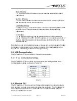
5.3.1. Virtual Communication Settings 

 
The TITAN-SVX-ETH uses same communication port settings as the serial 
communication setting as shown in Table 5.0. 
 

Parameter 

Setting 

Baud Rate 

115,200 

Byte Size 

8 bits 

Parity 

None 

Flow Control 

None 

Stop Bit 


Table 5.1 


5.4. Windows GUI 

The TITAN-SVX-ETH comes with a Windows GUI program to setup, configure, 
test, program, compile, download, and debug the controller.  The Windows GUI 
will perform all communication via RS-485.  See TITAN-SVX-ETH Software 
Users Manual for more details. 

Содержание TITAN-SVX-ETH

Страница 1: ...TITAN SVX ETH Hardware Manual page 1 Rev 4 03 HARDWARE MANUAL Revision 4 03 TITAN SVX ETH UNIVERSAL SERVO MOTOR CONTROLLER...

Страница 2: ...ights this document You may not reproduce or translate into any language in any form and means any part of this publication without the written permission from ARCUS ARCUS makes no representations or...

Страница 3: ...coder Input Circuit 12 4 4 MALE DSUB15 HD MOTION I O CONNECTOR 13 4 4 1 Pulse Direction CW CCW Inputs 14 4 4 2 Digital Outputs 15 4 5 3 PIN COMMUNICATION CONNECTION 16 4 6 USB COMMUNICATION CONNECTION...

Страница 4: ...tary Servo Motor 3 Phase Brushless Linear Servo Motor DC Voice Coil Motor In addition to the advanced servo motion control technology the TITAN SVX ETH also has a number of advanced control technologi...

Страница 5: ...ase Brushless Rotary Servo Motors 3 Phase Brushless Linear Servo Motors DC Voice Coil Motors Configurable in following modes Pulse Mode digital pulse control using pulse dir or CW CCW Control Mode int...

Страница 6: ...ts Main Power Input1 24 48 V 8 A Digital Input Forward Diode Current 25 mA Digital Output Collector Voltage 24 V Digital Output Sink Current 45 mA Operating Temperature2 20 80 C Storage Temperature2 5...

Страница 7: ...TITAN SVX ETH Hardware Manual page 7 Rev 4 03 3 Dimensions Figure 3 0...

Страница 8: ...d For high speed applications especially with the stepper motors 48VDC power supply is recommended Power pins and communication port pin outs are shown below Figure 4 0 Pin Name Description 1 V Power...

Страница 9: ...escription 1 V Motor V 2 U Motor U 3 W Motor W 4 NC No Connection Voice Coil Pin Name Description 1 Motor 2 Motor 3 NC No Connection 4 NC No Connection 2 Phase Bi Polar Stepper Motor Pin Name Descript...

Страница 10: ...or connector while the motor is enabled or when motor is moving Make sure to turn off the power to the controller or make sure that the motor is disabled when disconnecting the motor from the driver P...

Страница 11: ...ential Encoder B Signal Input 5 I EZ Differential Encoder Z Signal Input 6 I EZ Differential Encoder Z Signal Input 7 O 5V 5V for Encoder and Hall Power 8 O GND GND for Encoder and Hall Power 9 O A Si...

Страница 12: ...remental encoder inputs are accepted The maximum encoder input frequency is 3MHz See figure 4 3 for a circuit diagram of the encoder inputs Figure 4 3 Notes When using single ended encoders use the A...

Страница 13: ...nput Digital Input 2 4 I DIR DI2 Dir Input Digital Input 2 5 I ENA DI3 Enable Input Digital Input 3 6 I CLR DI4 Clear Fault Input Digital Input 4 7 I RST DI5 Reset Position Input Digital Input 5 8 I D...

Страница 14: ...of the movement Figure 4 5 Two clock uses CW as clockwise movement and CCW as counter clockwise movement Figure 4 6 Depending on the direction polarity setting actual direction of the stepper motor r...

Страница 15: ...to operate 4 4 3 Digital Inputs In Pulse Mode the following digital inputs are available Enable Reset and Clear Three other digital inputs are general purpose inputs In Control Mode the following digi...

Страница 16: ...communication Figure 4 10 Pin Name Description 1 485 Positive RS485 Signal 2 485 Negative RS485 Signal 3 GND Ground Table 4 4 4 6 USB Communication Connection TITAN SVX ETH supports USB 2 0 communicat...

Страница 17: ...ss of the TITAN SVX ETH 5 2 Serial Communication The TITAN SVX ETH communicates over an RS 485 interface 5 2 1 Communication Port Settings The TITAN SVX ETH has communication port settings as shown in...

Страница 18: ...lectrical reflections on the RS 485 network Note that on short communication buses or buses with a small number of nodes termination resistors may not be needed Inclusion of terminal resistors when th...

Страница 19: ...Contact Information Arcus Servo Motion Inc 3159 Independence Drive Livermore CA 94551 925 373 8800 www arcusservo com The information in this document is believed to be accurate at the time of public...

Отзывы: