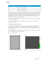
8.2 CPU module
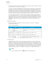
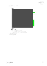
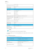
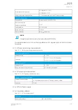
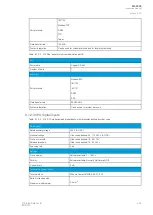
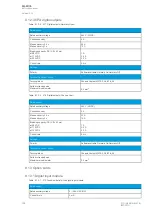
Figure. 8.2 - 247. CPU module.
Connector
Description
COM A
Communication port A, or the RJ-45 port. Used for the setting tool connection and for IEC 61850, Modbus/
TCP, IEC 104, DNP3 and station bus communications.
COM B
Communication port B, or the RS-485 port. Used for the SCADA communications for the following protocols:
Modbus/RTU, Modbus I/O, SPA, DNP3, IEC 101 and IEC 103. The pins have the following designations: Pin 1
= DATA +, Pin 2 = DATA –, Pin 3 = GND, Pins 4 & 5 = Terminator resistor enabled by shorting.
X1-1
Digital input 1, nominal threshold voltage 24 V, 110 V or 220 V.
X1-2
Digital input 2, nominal threshold voltage 24 V, 110 V or 220 V.
X1-3
Digital input 3, nominal threshold voltage 24 V, 110 V or 220 V.
X1-4
Common GND for digital inputs 1, 2 and 3.
X1-5:6
Output relay 1, with a normally open (NO) contact.
X1-7:8
Output relay 2, with a normally open (NO) contact.
X1-9:10
Output relay 3, with a normally open (NO) contact.
X1-11:12
Output relay 4, with a normally open (NO) contact.
X1-13:14:15 Output relay 5, with a changeover contact.
X1-16:17:18 System fault's output relay, with a changeover contact. Pins 16 and 17 are closed when the unit has a system
fault or is powered OFF. Pins 16 and 18 are closed when the unit is powered ON and there is no system fault.
X1-19:20
Power supply IN. Either 85…265 VAC/DC (model A; order code "H") or 18…75 DC (model B; order code
"L"). PPositiv
ositive side
e side (+) tto P
o Pin 20.
in 20.
GND
The relay's earthing connector.
A
AQ
Q-F205
-F205
Instruction manual
Version: 2.04
© Arcteq Relays Ltd
IM00013
379
Содержание AQ F205
Страница 1: ...AQ F205 Feeder protection IED Instruction manual ...
Страница 2: ......
Страница 379: ...Figure 7 4 245 Example block scheme A AQ Q F205 F205 Instruction manual Version 2 04 Arcteq Relays Ltd IM00013 377 ...
Страница 389: ...Figure 8 7 254 Device installation A AQ Q F205 F205 Instruction manual Version 2 04 Arcteq Relays Ltd IM00013 387 ...


