
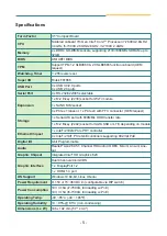


- 8 -
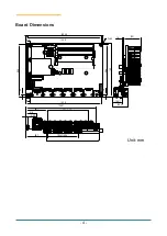
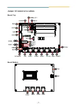
Jumpers
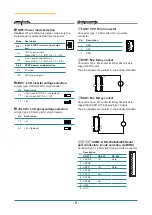
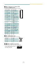
➊
SW1: Power mode selection
Caution:
When setting this jumper, make sure the
motherboard is disconnected from the power.
Mode
Description
ON
2
1
ON
2
1
ON
2
1
ON
2
1
Pin 1
Input & LVDS inverter power selec-
tion
On
15~36V power input
When JINV1 = 1-2, INV1 Pin 1, 2 = 12V
Off
9~15V power input (default)
When JINV1 = 1-2, INV1 Pin 1, 2 = 6.8V
Pin 2
AT/ATX power mode selection
On
AT mode
Off
ATX mode (default)
➋
JINV1: LCD inverter voltage selection
Jumper type: 2.00mm pitch 1x3-pin header
Pin
Description
1-2
+12V, when SW1 Pin1 = On (default)
+6.8V, when SW1 Pin1 = Off
2
3
1
2-3
+5V
2
3
1
➌
JVLCD1: LCD panel voltage selection
Jumper type: 2.00mm pitch 1x3-pin header
Pin
Description
1-2
+5V
2
3
1
2-3
+3.3V (default)
2
3
1
Connectors
①
FAN1: CPU Fan Connector
Connector type: 1.25mm pitch 1x3-pin wafer
connector.
Pin
Description
1
1
GND
2
VCC
3
RPM
②
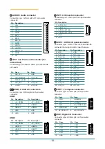
WIFI1: M.2 E-Key socket
Connector Type: M.2 socket for E-Key 22x30 type to
support WiFI module
The pin assignments conform to the industry standard.
75
74
33
23
22
32
E
1
2
③
SSD1: M.2 B-Key socket
Connector Type: M.2 socket for B-Key 22x42 type to
support SATA SSD or LTE depending on module
The pin assignments conform to the industry standard.
75
74
20
M
21
11
10
1
2
④⑤⑥⑦
COM1-4: RS-232/422/485 Serial
port connectors (mode selection via BIOS)
Connector type: 1.25mm pitch 1x9-pin wafer connector
Pin
Description
1
RS-232
RS-422
RS-485
1 XDCD#
TX-
Data-
2 XDSR#
3 XRXD
TX+
Data+
4 XRTS#
5 XTXD
RX+
6 XCTS#
7 XDTR#
RX-
8 XRI#
9 GND


