background image

- 74 -

Appendices

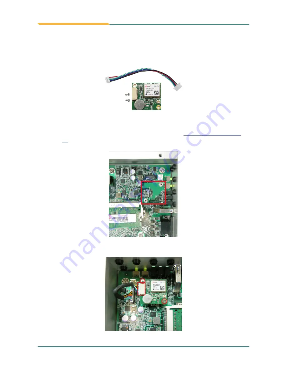
Appendix C: GPS Module Hardware Installation

1.  GPS Module kit is consist of GPS module, 2 screws, and one cable.

2.  Remove the computer’s bottom cover as described in 

4.1.1. Open the Computer

 on 

page 

40

.

3.  Locate the GPS screw hole on the mainboard

4. 

Fasten 2 screws to fix the module and connect the cable to the connector on the 

module. 

Содержание ARTS-1450

Страница 1: ...1 ARTS 1450 Fanless Vehicle PC with Intel Atom E3845 User s Manual Version 1 0 2015 03 P N 4012145000100P...

Страница 2: ...2 Revision History Version Release Time Description 1 0 March 2015 Initial release...

Страница 3: ...hapter 2 Getting Started 7 2 1 Dimensions 8 2 2 Take A Tour 9 2 3 Driver Installation Notes 11 Chapter 3 System Configuration 13 3 1 Board Layout 14 3 1 1 Main Boards 14 3 2 Jumpers and Connectors 16...

Страница 4: ...SATA Configuration 56 5 2 4 SIO Fintek 81216 57 5 2 5 H W Monitor 57 5 3 Security 58 5 4 Power 59 5 5 Boot 60 5 6 Exit 61 Appendices 63 Appendix A HSPA 1450 Hardware Installation 64 Appendix B WIFI A...

Страница 5: ...turer Declaration of Conformity CE The CE symbol on the computer indicates that it is in compliance with the directives of the Union European EU ACertificate of Compliance is available by contacting T...

Страница 6: ...ve was published on 2 13 2003 The main purpose of the directive is to prohibit the use of lead mercury cadmium hexavalent chromium polybrominated biphenyls PBB and polybrominated diphenyl ethers PBDE...

Страница 7: ...o not place anything over the power cord 8 Never pour any liquid into opening This may cause fire or electrical shock 9 Never open the equipment For safety reasons the equipment should be opened only...

Страница 8: ...whenever components are separated from the system Replacing Lithium Battery Incorrect replacement of the lithium battery may lead to a risk of explosion The lithium battery must be replaced with an id...

Страница 9: ...e misuse of or inability to use this product Vendor will not be liable for any claim made by any other related party Vendors disclaim all other warranties either expressed or implied including but not...

Страница 10: ...viii This page is intentionally left blank...

Страница 11: ...1 1 Chapter 1 Introduction Chapter 1 Introduction...

Страница 12: ...Dou and QZSS singals Compliant with MIL STD 810G Optional CAN BUS2 0B and 4 channel CCTV 4 x COM 1 x USB3 0 2 x USB2 0 4 in 4 out GPIO 1 2 About this Manual This manual is meant for the experienced us...

Страница 13: ...V w DB 9 connector USB Port 1 x type A USB 3 0 port front side 2 x type A USB 2 0 ports rear side LAN Port 1 x RJ 45 port for GbE rear side Video Port 1 x DVI D female connector rear side 1 x VGA with...

Страница 14: ...L STD 810G Method 514 6 Category 24 minimum integrity test Shock Operating MIL STD 810G Method 516 6 Procedure functional shock 20g Non operating MIL STD 810G Method 516 6 Procedure V crash hazard shi...

Страница 15: ...ain the following items ARTS 1450 Fanless Vehicle PC One Driver CD One User s Manual 1 5 Ordering Information ARTS 1450 Vehicle Barebone System w Intel Atom Quad core E3845 SoC w o memory and storage...

Страница 16: ...MM 3IL 2G Industrial grade DDR3L 1600 2GB SDRAM MM 3IL 4G Industrial grade DDR3L 1600 4GB SDRAM MM 3IL 8G Industrial grade DDR3L 1600 8GB SDRAM WIFI AT2350 Atheros AR9462 WiFi module w 20cm 30cm inter...

Страница 17: ...7 2 Chapter 2 Getting Started Chapter 2 Getting Started...

Страница 18: ...llustration shows the dimensions of the computer with the measurements in width depth and height called out 54 00 200 00 225 50 212 00 100 00 Unit mm 18 00 10 00 5 50 180 00 40 00 COM1 COM2 COM3 COM4...

Страница 19: ...pped up by plugs Reset button accessible with a pin SD card slot USB 3 0 port SIM1 2 card slots DIO port LED Indicators Status LED Lamps No LED Color Description Red This LED flashes red when SSD is b...

Страница 20: ...10 Getting Started Rear View Power jack DVI D port RS232 485 serial ports RS232 serial ports USB ports LAN port VGA Fuse Audio port...

Страница 21: ...81_R275 exe Ethernet 32Bit Ethernet Win7 PROWin32 exe 64Bit Ethernet Win7 PROWinx64 exe Processor IO 32Bit Processor IO Win7 545318_545318_Intel_Processor_Win7_IO_ Drivers_Gold_v2_0 Intel Processor Wi...

Страница 22: ...12 This page is intentionally left blank...

Страница 23: ...13 3 Chapter 3 System Configuration Chapter 3 System Configuration...

Страница 24: ...FMB i2310 Board Top 2 72 74 204 203 ON 2 1 6 5 2 1 1 9 1 13 14 1 2 1 10 9 2 11 6 1 15 10 5 1 1 1 10 9 2 1 10 9 2 3 1 4 3 2 1 5 6 7 8 9 1 4 3 2 1 3 2 1 1 3 4 2 1 3 4 2 1 C6 C5 C4 C3 C2 C1 SW1 SW2 1 2...

Страница 25: ...1 6 1 2 1 1 7 5 1 1 2 8 7 1 2 8 7 1 8 7 4 3 2 1 4 3 2 1 4 3 2 1 4 3 2 1 G S D G S D 1 4 5 8 1 4 5 8 1 4 5 8 1 4 5 8 1 4 5 8 1 4 5 8 1 4 5 8 8 5 4 C E B C E B C E B C E B C E B C E B 2 0 1 1 1 0 D S G...

Страница 26: ...tting Short pin 1 and pin 2 to keep CMOS The default setting 2 3 1 Short pin 2 and pin 3 to clear CMOS 2 3 1 Board Top 2 72 74 204 203 ON 2 1 6 5 2 1 1 9 1 13 14 1 2 1 10 9 2 11 6 1 15 10 5 1 1 1 10 9...

Страница 27: ...ON 2 1 6 5 2 1 1 9 1 13 14 1 2 1 10 9 2 11 6 1 15 10 5 1 1 1 10 9 2 1 10 9 2 3 1 4 3 2 1 5 6 7 8 9 1 4 3 2 1 3 2 1 1 3 4 2 1 3 4 2 1 C6 C5 C4 C3 C2 C1 SW1 SW2 1 2 3 4 5 6 7 1 2 10 5 9 1 6 5 9 1 6 22...

Страница 28: ...KE ON Board Top 2 72 74 204 203 ON 2 1 6 5 2 1 1 9 1 13 14 1 2 1 10 9 2 11 6 1 15 10 5 1 1 1 10 9 2 1 10 9 2 3 1 4 3 2 1 5 6 7 8 9 1 4 3 2 1 3 2 1 1 3 4 2 1 3 4 2 1 C6 C5 C4 C3 C2 C1 SW1 SW2 1 2 3 4...

Страница 29: ...ON 2 1 6 5 2 1 1 9 1 13 14 1 2 1 10 9 2 11 6 1 15 10 5 1 1 1 10 9 2 1 10 9 2 3 1 4 3 2 1 5 6 7 8 9 1 4 3 2 1 3 2 1 1 3 4 2 1 3 4 2 1 C6 C5 C4 C3 C2 C1 SW1 SW2 1 2 3 4 5 6 7 1 2 10 5 9 1 6 5 9 1 6 22 2...

Страница 30: ...RST Board Top 2 72 74 204 203 ON 2 1 6 5 2 1 1 9 1 13 14 1 2 1 10 9 2 11 6 1 15 10 5 1 1 1 10 9 2 1 10 9 2 3 1 4 3 2 1 5 6 7 8 9 1 4 3 2 1 3 2 1 1 3 4 2 1 3 4 2 1 C6 C5 C4 C3 C2 C1 SW1 SW2 1 2 3 4 5 6...

Страница 31: ...op 2 72 74 204 203 ON 2 1 6 5 2 1 1 9 1 13 14 1 2 1 10 9 2 11 6 1 15 10 5 1 1 1 10 9 2 1 10 9 2 3 1 4 3 2 1 5 6 7 8 9 1 4 3 2 1 3 2 1 1 3 4 2 1 3 4 2 1 C6 C5 C4 C3 C2 C1 SW1 SW2 1 2 3 4 5 6 7 1 2 10 5...

Страница 32: ...4 203 ON 2 1 6 5 2 1 1 9 1 13 14 1 2 1 10 9 2 11 6 1 15 10 5 1 1 1 10 9 2 1 10 9 2 3 1 4 3 2 1 5 6 7 8 9 1 4 3 2 1 3 2 1 1 3 4 2 1 3 4 2 1 C6 C5 C4 C3 C2 C1 SW1 SW2 1 2 3 4 5 6 7 1 2 10 5 9 1 6 5 9 1...

Страница 33: ...Function RS 232 485 Port 1 5 9 6 Connector Type External 9 pin D sub male connector Pin Description Pin Description 1 DCD RS485 6 DSR 2 RXD RS485 7 RTS 3 TXD 8 CTS 4 DTR 9 RI 5 GND Board Top COM1 COM2...

Страница 34: ...24 System Configuration PWRIN1 Function Power Input Connector 1 2 3 Connector Type 3 pin terminal block Pin Description 1 VIN 2 VIN 3 ACC_ON Board Top COM1 COM2 COM3 COM4 DVI D ACC DC in 9 36V...

Страница 35: ...74 204 203 ON 2 1 6 5 2 1 1 9 1 13 14 1 2 1 10 9 2 11 6 1 15 10 5 1 1 1 10 9 2 1 10 9 2 3 1 4 3 2 1 5 6 7 8 9 1 4 3 2 1 3 2 1 1 3 4 2 1 3 4 2 1 C6 C5 C4 C3 C2 C1 SW1 SW2 1 2 3 4 5 6 7 1 2 10 5 9 1 6 5...

Страница 36: ...3 VCC5 14 CAN_L Board Top 2 72 74 204 203 ON 2 1 6 5 2 1 1 9 1 13 14 1 2 1 10 9 2 11 6 1 15 10 5 1 1 1 10 9 2 1 10 9 2 3 1 4 3 2 1 5 6 7 8 9 1 4 3 2 1 3 2 1 1 3 4 2 1 3 4 2 1 C6 C5 C4 C3 C2 C1 SW1 SW2...

Страница 37: ...Board Top 2 72 74 204 203 ON 2 1 6 5 2 1 1 9 1 13 14 1 2 1 10 9 2 11 6 1 15 10 5 1 1 1 10 9 2 1 10 9 2 3 1 4 3 2 1 5 6 7 8 9 1 4 3 2 1 3 2 1 1 3 4 2 1 3 4 2 1 C6 C5 C4 C3 C2 C1 SW1 SW2 1 2 3 4 5 6 7 1...

Страница 38: ...7 RTS 8 CTS 9 RI 10 N C Board Top COM1 COM2 COM3 COM4 DVI D ACC DC in 9 36V JDIO1 Description DIGITAL SINGAL INPUT AND OUTPUT Connector Type DSUB 15 Male Connector 1 11 15 5 Pin Description Pin Descri...

Страница 39: ...9 1 13 14 1 2 1 10 9 2 11 6 1 15 10 5 1 1 1 10 9 2 1 10 9 2 3 1 4 3 2 1 5 6 7 8 9 1 4 3 2 1 3 2 1 1 3 4 2 1 3 4 2 1 C6 C5 C4 C3 C2 C1 SW1 SW2 1 2 3 4 5 6 7 1 2 10 5 9 1 6 5 9 1 6 22 23 24 25 1 2 3 4...

Страница 40: ...203 ON 2 1 6 5 2 1 1 9 1 13 14 1 2 1 10 9 2 11 6 1 15 10 5 1 1 1 10 9 2 1 10 9 2 3 1 4 3 2 1 5 6 7 8 9 1 4 3 2 1 3 2 1 1 3 4 2 1 3 4 2 1 C6 C5 C4 C3 C2 C1 SW1 SW2 1 2 3 4 5 6 7 1 2 10 5 9 1 6 5 9 1 6...

Страница 41: ...25 PERp0 37 GND 48 1 5V 11 REFCLK 26 GND 38 USB_D 49 Reserved 12 UIM_CLK 27 GND 39 3 3V 50 GND 13 REFCLK 28 1 5V 40 GND 51 Reserved 14 UIM_RESET 29 GND 41 3 3V 52 3 3V 15 GND 30 SMB_CLK 42 LED_WWAN 5...

Страница 42: ...36 USB_D 47 Reserved 11 REFCLK 26 GND 37 GND 48 1 5V 12 UIM_CLK 27 GND 38 USB_D 49 Reserved 13 REFCLK 28 1 5V 39 3 3V 50 GND 14 UIM_RESET 29 GND 40 GND 51 Reserved 15 GND 30 SMB_CLK 41 3 3V 52 3 3V 5...

Страница 43: ...NC 13 NC 32 NC 48 NC 14 NC 33 RX 49 NC 15 GND 34 GND 50 GND 16 NC 35 GND 51 NC 17 NC 52 3 3V 18 GND 19 NC 52 51 16 18 15 17 2 1 Board Top 2 72 74 204 203 ON 2 1 6 5 2 1 1 9 1 13 14 1 2 1 10 9 2 11 6 1...

Страница 44: ...ports Connector type RJ 45 connector with LED Double stacked type A USB 2 0 connectors Pin Description Pin Description 1 MDI0 5 MDI2 2 MDI0 6 MDI2 3 MDI1 7 MDI3 4 MDI1 8 MDI3 Pin Description 1 5V 2 U...

Страница 45: ...35 System Configuration VGA1 Function Analog RGB DVI D Connector Connector type Analog RGB D Sub 15 pin female type DVI D DVI D female connector DVI D COM1 COM2 COM3 COM4 DVI D ACC DC in 9 36V...

Страница 46: ...72 74 204 203 ON 2 1 6 5 2 1 1 9 1 13 14 1 2 1 10 9 2 11 6 1 15 10 5 1 1 1 10 9 2 1 10 9 2 3 1 4 3 2 1 5 6 7 8 9 1 4 3 2 1 3 2 1 1 3 4 2 1 3 4 2 1 C6 C5 C4 C3 C2 C1 SW1 SW2 1 2 3 4 5 6 7 1 2 10 5 9 1...

Страница 47: ...6 1 2 1 1 7 5 1 1 2 8 7 1 2 8 7 1 8 7 4 3 2 1 4 3 2 1 4 3 2 1 4 3 2 1 G S D G S D 1 4 5 8 1 4 5 8 1 4 5 8 1 4 5 8 1 4 5 8 1 4 5 8 1 4 5 8 8 5 4 C E B C E B C E B C E B C E B C E B 2 0 1 1 1 0 D S G D...

Страница 48: ...MS Board Top 2 72 74 204 203 ON 2 1 6 5 2 1 1 9 1 13 14 1 2 1 10 9 2 11 6 1 15 10 5 1 1 1 10 9 2 1 10 9 2 3 1 4 3 2 1 5 6 7 8 9 1 4 3 2 1 3 2 1 1 3 4 2 1 3 4 2 1 C6 C5 C4 C3 C2 C1 SW1 SW2 1 2 3 4 5 6...

Страница 49: ...39 4 Chapter 4 Installation and Maintenance Chapter 4 Installation and Maintenance...

Страница 50: ...xpress Mini card sockets are built on the carrier board To access these components the computer s top cover has to go Follow through the steps below to remove the top cover from the computer 1 Place t...

Страница 51: ...sible SIM card slot Follow through the guide below to install a SIM card to the computer To install a SIM card 1 On the front panel of the computer find the SIM card slot door Loose the screw to open...

Страница 52: ...cted in the illustration below Push insert the SIM card into the slot Push insert the SIM card To uninstall the SIM card 1 Use a cliper to press the eject button to eject the SIM card 2 Pull out the S...

Страница 53: ...one 2 5 inch SSD storage devices To install a 2 5 SSD to the computer follow through the guide below 1 Open the Computer as instruction of 4 1 1 Open the Computer on page 40 2 Locate the bracket insid...

Страница 54: ...44 Installation Maintenance 3 Insert the 2 5 inch SSD into the connector on the bracket 4 Fix the SSD with 2 screws 5 Put the bracket with the SSD back to the computer plug cables and fasten screws...

Страница 55: ...emble SSD bracket Before Wi Fi 3G mSATA module Installation please remove the 2 5 SSD bracket 1 Open the Computer as instruction of 4 1 1 Open the Computer on page 40 2 Unplug the cables and loose the...

Страница 56: ...Installation Maintenance 4 1 5 Install Memory Module on CPU Module 1 Open the computer as 4 1 1 Open the Computer 2 Locate the Memory module slot and insert the memory module 3 Assemble the bottom co...

Страница 57: ...nce 4 1 6 Insert a SD card 1 On the front panel of the computer find the SD card slot door Loose the screw to open it 2 Slide the SD card into the slot You can hear a slight clicking noise which means...

Страница 58: ...ion Maintenance 4 2 Mount the Computer Follow through the guide below to mount the computer to a wall 1 Find the four cutouts as marked in the illustration below 2 Mount the computer to a wall by the...

Страница 59: ...ut wires of the DC power source 5 Identify the positive and negative feed positions for the terminal block connection See the symbols printed on the rear panel indicating the polarities and DC input p...

Страница 60: ...itive and negative feed positions for the terminal block connection See the symbols printed on the rear panel indicating the polarities and DC input power range in voltage 6 Insert the exposed wires i...

Страница 61: ...51 5 Chapter 5 BIOS Chapter 5 BIOS...

Страница 62: ...ject Name ARTS 1450 Build Date 09 25 2014 Build Time 13 58 36 System Date System Time 10 04 19 01 28 2015 Advanced Security Power Boot Exit Main Processor Intel R Atom TM CPU E3485 1 91GHz System Bus...

Страница 63: ...current value to the next higher value or switches between available options F6 Decreases current value to the next lower value or switches between available options F1 Opens the Help of the BIOS Setu...

Страница 64: ...or Intel R Atom TM CPU E3485 1 91GHz System Bus Speed 83 MHz System Memory Speed 1333 MHz Cache RAM 1024 KB Total Memory 2048 MB Change Values F5 F6 Select SubMenu Enter Select Item Select Menu F1 Exi...

Страница 65: ...ek 81216 H W Monitor Change Values F5 F6 Select SubMenu Enter Select Item Select Menu F1 Exit ESC Help Setup Defaults F9 Save and Exit F10 The featured settings and submenus are Setting Description Bo...

Страница 66: ...Options are Disable disables ASPM L0s force all links to L0s state L1 force all links to L1 state L0sL1 force all links to L0s L1 state Auto BIOS auto configure 5 2 3 SATA Configuration Select this su...

Страница 67: ...ce Set the mode of Serial port Options RS232 default RS485 Interrupt Set the interrupt of Serial port Serial Port 3 4 Enable default or Disable Serial Port COM Base I O Address Set the Base I O addres...

Страница 68: ...t Supervisor Password Change Values F5 F6 Select SubMenu Enter Select Item Select Menu F1 Exit ESC Help Setup Defaults F9 Save and Exit F10 Install or change the password and the length of password mu...

Страница 69: ...disables Wake on PME Determines the action taken when the system power is off and a PCI Power Management Enable wake up event occurs State After G3 Set the state of System when power is re applied aft...

Страница 70: ...Boot Enabled ACPI Selection ACPI 4 0 Timeout 0 Change Values F5 F6 Select SubMenu Enter Select Item Select Menu F1 Exit ESC Help Setup Defaults F9 Save and Exit F10 The featured settings are Setting...

Страница 71: ...lues F5 F6 Select SubMenu Enter Select Item Select Menu F1 Exit ESC Help Setup Defaults F9 Save and Exit F10 The features settings are Setting Description Exit Saving Changes Exit system setup after s...

Страница 72: ...62 This page is intentionally left blank...

Страница 73: ...63 Appendices Appendices...

Страница 74: ...you to install the 3G module HSPA 1450 1 Remove the computer s bottom cover as described in 4 1 1 Open the Computer on page 40 The inside of the computer comes to view 2 To remove the SSD bracket plea...

Страница 75: ...factor with two U FL connectors one is ANT1 and the other is ANT2 Two U FL connectors one is ANT1 the other is ANT2 5 Plug the 3G module to the socket s connector by a slanted angle Fully plug the mod...

Страница 76: ...ews 7 Have the RF antenna The antenna has an SMA connector on one end and an MHF connector on the other SMA connector MHF connector 8 Connect the RF antenna s MHF connector to the 3G module s ANT1 con...

Страница 77: ...ector remove the washer and the nut Save the washer and nut for later use Note the SMA connector has the form of a threaded bolt with one flattened side Remove the nut and washer Among the screw threa...

Страница 78: ...then the nut to the SMA connector Make sure the nut is tightened Mount the washer and the nut to the SMA connector Tighten the nut 13 Have an external antenna Screw and tightly fasten the antenna to t...

Страница 79: ...dix will guide you to install the Wi Fi module WIFI AT2350 1 Remove the computer s bottom cover as described in 4 1 1 Open the Computer on page 40 The inside of the computer comes to view 2 To remove...

Страница 80: ...two U FL connectors one is 1 and the other is 0 Bluetooth ANT0 Main WiFi ANT1 Main ANT0 AUX 5 Plug the Wi Fi module to the socket s connector by a slanted angle Fully plug the module and note the notc...

Страница 81: ...onnector MHF connector 8 Connect the RF antenna s MHF connector to the Wi Fi module s MAIN connector Connect the RF antenna s MHF connector to the WiFi module s 1 connector 9 Remove one plastic plug f...

Страница 82: ...washer Among the screw thread there is a flat side 11 Pull the SMA connector through the above mentioned antenna hole Note to meet the aforesaid flattened side with the antenna hole s flat side Arran...

Страница 83: ...73 Appendices 13 Have an external antenna Screw and tightly fasten the antenna to the SMAconnector...

Страница 84: ...it is consist of GPS module 2 screws and one cable 2 Remove the computer s bottom cover as described in 4 1 1 Open the Computer on page 40 3 Locate the GPS screw hole on the mainboard 4 Fasten 2 screw...

Страница 85: ...nect the RF antenna s MHF connector to the GPS module s ANT1 connector 7 From the other end of the RF antenna which is an SMA connector remove the washer and the nut Save the washer and nut for later...

Страница 86: ...e s flat side Arrange the flat side of the SMA connector to meet the flat side of the antenna hole 9 Mount the washer first and then the nut to the SMA connector Make sure the nut is tightened Mount t...

Страница 87: ...dule Hardware Installation 1 CANBUS Module kit is consist of CANBUS module one rubber and one cable 2 Remove the computer s bottom cover as described in 4 1 1 Open the Computer on page 40 3 Locate the...

Страница 88: ...78 Appendices 4 Remove the tap on the rubber and attach the rubber to the main board as shown 5 Insert the CANBUS module into the connector 6 Plug the CANBUS cable into the connector...

Страница 89: ...crews of the COM3 or COM4 to remove the D Sub connector 8 Pull the D Sub connector through the D Sub hole and fix it with the stand off hex screws 9 Attach one rubber to the SSD bracket to protect the...

Отзывы: